Injection Molding: A Practical Approach to Calculating Residence Time
Toss the formulas. The best way to determine residence time is to conduct a simple experiment.
During the introduction to my seminars, I often present this definition of injection molding developed by legendary consultant and Plastics Hall of Famer Glenn Beall: “Injection molding is a jungle of disconnected facts and fairy tales.” The fairy-tale aspect is true for many residence-time calculations that are bantered about in our industry. Unfortunately, the cynic in me—when I shift to Crusty Sr. mode—looks at them with more than a little suspicion.
They look good and follow reasonable logic, but yet do not cut it when you want good data. So, how do I find out the true residence time? This is where the “Scientific” in Scientific Molding comes in.
You do an experiment to get “Scientific” data—data that should verify a formula that appears to cover the bases. Most of the formulas used to calculate residence time are based on barrel capacity, percent of the barrel used, cycle time, etc. All logical, but if you spend some real time on and around an injection molding machine, especially when a screw is pulled, you notice there are issues that these formulas do not take into consideration. Several were covered in an Extrusion Know-How column Jim Frankland wrote (“Dead Screw Talking”) in July 2011.
True, he deals with extrusion, but like it or not, extrusion people have more savvy on the matter of screw design then most of us A Practical Approach to Calculating Residence Time molders. For our purpose of finding residence time, it does not matter what type of screw you have, but we will base this on the typical general-purpose (GP) screw. Frankland calls GP screws “no-purpose” screws. While I agree, and I don’t recommend using one, in reality such designs are the most common in molding. For a 20:1 length-to-diameter (L/D) GP screw, this means 10 flights of feed, five flights of transition or compression, and five flights of metering. A 20:1 L/D is my recommended minimum L/D for molding.
Residence time at high temperatures causes polymer degradation.
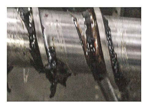
The concept is that the resin pellets enter through the feed throat and travel through the feed, transition and metering sections, passing from one flight to the next. But inspection of used screws reveals that there is more to the story. In particular, focus on the hangup or “dead space” at the base of the flights, both the front and the back sides.
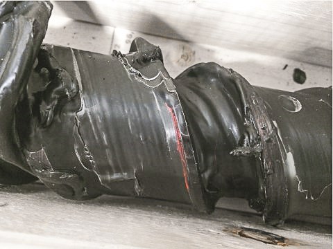
Figures 1 and 2 provide examples. Figure 1 shows significant degradation of a clear resin. How did this material “hang up” or remain too long in the dead spaces of the flights? Residence time at high temperatures causes polymer degradation. Figure 2 shows a red resin clinging to the screw flight. This red material “hung up” for over a month as this machine was switched to black and ran only black for the next month before the screw was pulled for cleaning.
At first, this molder insisted the plant only ran black, never any other color. The screw tells a different tale (as did the molder’s manufacturing supervisor upon further reflection). Seems that they had a short run of red a month earlier. Bottom line: Screws have “dead spaces” where material can get trapped for significant periods of time. Hence the frequent “carbon showers” we all have tried in vain to purge out. Such trapped resin is seen nearly 90% of the time with injection molding screws when pulled for service, especially those that have not been cleaned for months. So, what has this got to do with residence time? It forces one to put a fudge factor into the equations that calculate residence time.
How long does it take for the resin to move from one flight to another? It is anybody’s guess, and that throws out the formulas or equations. What is left to find residence time? As mentioned earlier, an experiment! One that will provide you with a more realistic residence time. With the machine running on cycle allow the existing resin to run until you can see the flights of the feed section. Carefully move the hopper off the feed throat. Please do not look down into the feed throat without goggles—better yet, use a highly polished metal mirror and a flashlight to watch until you can see a couple of flights are empty.
The entire feed section does not have to be empty, just the flights visible as the screw turns. As soon as these rear feed flights are empty, drop in a few different colored granules of the same resin followed by the normal original resin (move the hopper back). Immediately start counting shots, keeping track until the different color appears and purges out. That is, keep counting shots until the different color is gone and only the original resin color is in the parts. Now get the calculator and multiply the number of shots times the cycle time.
Bottom line: measure the residence, toss the formulas. Check it out for yourself. I’m pretty sure I will get some arguments about stopping as soon as you see the different color but give the purge-out time some thought. Also, take note on how the new color appears in the parts. It should be a pastel of the mixed colors. Any swirls, streaks, etc. and you have just proven you do not have melt uniformity. Then it will be time to consider problems with the GP screw design.
ABOUT THE AUTHOR: John Bozzelli is the founder of Injection Molding Solutions (Scientific Molding) in Midland, Mich., a provider of training and consulting services to injection molders, including LIMS, and other specialties. Contact john@scientificmolding.com; scientificmolding.com.
Related Content
Use These 7 Parameters to Unravel the Melt Temperature Mystery
Despite its integral role in a stable process and consistent parts, true melt temperature in injection molding can be an enigma. Learning more about these seven parameters may help you solve the puzzle.
Read MoreOnline Versions of Process Development Course and Software Launch
NPE2024: FimmTech is introducing online versions of its Nautilus process development software as well as its Scientific Molding and Design of Experiments (DOE) process development course.
Read MoreRead Next
Making the Circular Economy a Reality
Driven by brand owner demands and new worldwide legislation, the entire supply chain is working toward the shift to circularity, with some evidence the circular economy has already begun.
Read MorePeople 4.0 – How to Get Buy-In from Your Staff for Industry 4.0 Systems
Implementing a production monitoring system as the foundation of a ‘smart factory’ is about integrating people with new technology as much as it is about integrating machines and computers. Here are tips from a company that has gone through the process.
Read More
.jpg;width=70;height=70;mode=crop)


