Use These 7 Parameters to Unravel the Melt Temperature Mystery
Despite its integral role in a stable process and consistent parts, true melt temperature in injection molding can be an enigma. Learning more about these seven parameters may help you solve the puzzle.
As an engineer, I am always struck at how some of the simplest questions in our field are the most difficult to answer. For example, if I were to approach a process engineer at a machine and ask, “What temperature are you running the plastic at on this machine” or, more specifically, “What is the actual melt temperature of the plastic as it leaves the machine nozzle tip orifice?”
Inevitably, I will receive various responses ranging from “I’m not sure” and “I don’t know” to someone citing the recommended barrel temperature ranges from the material suppliers’ processing guidelines. Alternatively, the process engineer might review the barrel temperature set points on the machine controller and make a guess or approximation.
I do not fault the process engineer for any uncertainty because I’m actually asking a difficult and potentially “trick” thermodynamic question. When conducting a public or private injection molding training, a hypothetical question that I enjoy asking is: What is the actual plastic temperature for a process utilizing a flat barrel profile of 400°F, hydraulic back pressure of 50 psi, screw rotation speed of 75 rpm and a cycle time of 30 seconds? Is it above 400°F, at 400°F, below 400°F or could it be any of these?
Most responses are above 400°F, however, the correct answer is it could be any of them. The reason being is I have not given you enough information to truly answer the question. Is the material amorphous or semicrystalline; what is the material residence time; what is the screw configuration; what is the machine-intensification ratio to convert the hydraulic pressure to plastic pressure? These are just a few unknowns that make it difficult to answer this question.
It is my experience that a molder rarely knows the L/D or compression ratios for their machine inventory and I have yet to see the compression ratio and rarely seen the L/D ratio noted on the manufacturer’s machine specifications.
To truly answer this question, one would need to conduct an air shot on machine cycle and measure it with either a needle nose pyrometer or an infrared device such as a camera. Using these two methods is not as repeatable or reproducible as we would desire because the procedure is not standardized. The measuring devices might not be calibrated; the emissivity of the object we are measuring with the infrared device is not precisely known; human error is possible; and typically it takes two individuals to conduct this measurement. With this in mind, to what degree of certainty can we determine if the measured temperature is reasonable, repeatable or reproducible?
As mentioned in our March 2024 article, “Understanding the Effect of Pressure Losses on Injection Molded Parts,” we can simplify the injection molding process by focusing on what the plastic “experiences” as it travels through the machine and into the mold. This perspective can be referred to as “Injection Molding from the Plastic’s Point of View” or Scientific Injection Molding.
There are many parameters that can be adjusted, but it is important to acknowledge adjustments will affect one or more of the four primary plastic processing conditions, which are:
- Plastic Temperature
- Plastic Flow Rate
- Plastic Pressure
- Plastic Cooling Rate and Time
With a machine or cycle time change, there are seven parameters that have a large influence on the actual plastic temperature:
- Residence Time
- Plastic Flow Rate
- Screw Configuration
- Barrel and Nozzle Heats
- Screw Speed or RPM
- Back Pressure
- Feed Throat Condition
- Residence Time
1. Residence Time
Residence time can be impacted by increasing or decreasing the amount of material the machine processes per hour or if the injection unit specifications have changed, which is common when moving molds among machines. The residence time is defined as the time a resin pellet is physically in the barrel and exposed to shearing or heating via conduction. Changing any time-related machine parameter — cooling time, packing time, holding time, mold open/close times, mold protection time, part ejection time and the addition or removal of a robot — will change the residence time.
There are other parameters or conditions that will affect the plastic temperature to a smaller degree but are still important such as: the nozzle-tip orifice; the use of a general-purpose or a reverse-taper nozzle tip; changes in resin moisture content; lot-to-lot resin variations; the use of color concentrates; the letdown ratio of the color concentrate; the use of regrind (including the amount, its size and its moisture content); resin pellet size and shape; the use of a static or dynamic mixing section; the screw rotate delay time; and the screw dwell time, which is the time between the completion of plastication and the end of the cooling time.
2. Plastic Flow Rate
It is important to note that the plastic flow rate is one of the four primary plastic processing conditions, and if we were conducting a Design of Experiments (DOE), we would find that the plastic flow rate and plastic temperature have a strong correlation. As the plastic flow rate is increased, the amount of internal heat generation or shear heat is increased. This phenomena, called drag flow, is due to the friction between the tool steel and the flowing polymer chains. Due to friction, a velocity profile or flow speed differences are developed along the cross section of the plastic with the plastic flowing slower near the wall and faster toward the center of the flow front.
The velocity profile causes the polymer chains to orient in the direction of flow, and these flow speed differences generate friction or shear heat between one plane of chains flowing faster than another plane of chains. This phenomenon exists regardless of the temperature difference between the tool steel and the melt temperature. In fact, a velocity profile or flow speed difference is generated when water is flowing through a pipe, however, shear heating is not observed nor is the reduction in viscosity for a non-Newtonian medium such as plastic.
3. Screw Configuration
Screw configuration is quite complex, but for the purposes of this article, we will focus on the length-to-diameter ratio (L/D) and the compression ratio for a general-purpose screw without a mixing section. General-purpose screws are commonly used because they can process a large range of thermoplastics. However, there are numerous screw configurations and screws designed for specific materials or molding specific types of injection molded parts, such as thin-wall packaging and PET preforms.
Nonetheless, it would be cumbersome and time consuming for an injection molder to change screws and potentially the barrel based on a material change. If a molding facility is dedicated to molding thin-wall packaging or PET preforms, it is highly likely that specific screw designs are used, as they will optimize melt homogeneity, plastic temperature, plasticizing capacity and cycle time.
The L/D ratio is represented in Figure 1 and mathematically defined by the following equation.

How to determine the L/D ratio for injection molding. Source: Orbital Consulting
Here L/D is the screw flighted length — ignoring the screw’s shank length and front-end components — divided by the screw diameter. For thermoplastics, the L/D ratio can range from 16:1 to 25:1, with 20:1 being the most common for general-purpose screws. Larger ratios increase plastic residence time; the amount of shear heat generated; and ultimately the plastic temperature. A ratio of 25:1 is common for packaging applications or molding PET preforms where larger amounts of shear heat are needed to bring the resin to its melt or processing temperature.
The depiction and simplified equation for the compression ratio is defined as the flight depth in the feed zone divided by the flight depth in the metering zone (See Figure 2). For thermoplastics, the compression ratio can vary from 1.5:1 to 4.5:1 with most general-purpose screws ranging from 2.0 to 3.5:1. Larger compression ratios increase shear heat, melt temperatures and the potential for melt degradation.
It is important to note that the thermocouples are measuring the steel temperature of the barrel and nozzle and not the actual plastic temperature inside. This is why simply reviewing the barrel set points will not provide the actual plastic temperature.
Unfortunately, it is my experience that molders rarely know the L/D or compression ratios for their machine inventory, and I have yet to see the compression ratio and rarely seen the L/D ratio noted on the machine manufacturer’s press specifications. This is a big unknown for most molders, and this lack of knowledge creates a large gap in understanding the plastic temperature and can potentially produce processing problems based solely on the screw configuration.
Problems I have observed over the years stemming from this knowledge gap include degraded material, marbelizing of the plastic, variations in color consistency and dimensional variations. Some of these issues were caused by not knowing a barrier screw design with a dynamic mixing section were being utilized.

The compression ratio considers the flight depths of the metering and feed zones of the screw. Source: Orbital Plastics Consulting
4. Barrel and Nozzle Heaters
These are placed around the circumference of the barrel and nozzle body. Via conduction, heat is transferred into the plastic to melt and soften the plastic. Changing the heater set points is one of the most efficient methods of changing the plastic temperature, especially in the front zone of the barrel where the flight depth is the most shallow and where the next shot of material resides. It is important to note that the thermocouples are measuring the steel temperature of the barrel and nozzle, and not the actual plastic temperature inside. This is why simply reviewing the barrel set points will not provide the actual plastic temperature.
When replacing heaters, it is important to note the heater band material, the width of the heater band, the precise location of the heater band and the wattage rating. If a heater band is not replaced and located properly, this will change the amount of heat generated via conduction and ultimately the plastic temperature. I have personally witnessed the incorrect replacement of heater bands, unknowingly, resulting in several hours of troubleshooting to determine why the unchanged barrel set points resulted in a noticeable change in the process and plastic temperature.
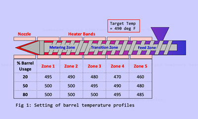
It is possible to utilize a flat, forward or reverse temperature profile down the length of the barrel, depending on the shot size, material type, screw design and residence time. A “hump” profile can be used by increasing the compression or transition zone of the barrel by 30 to 50°F, above the rear and front zones. In most conditions, it is ideal to set the front zone temperature to the desired plastic temperature.
5. Screw Rotation Speed and Back Pressure
During the plastication phase, the screw rotation speed and back pressure are adjustable, and increasing these can generate larger amounts of shear heat, thereby increasing plastic temperature. Back pressure is the pressure resisting the screw moving backward during screw rotation. A minimum amount must be utilized to compress the plastic down the length of the barrel, remove any air bubbles that may have been plasticized into the melt and to consistently control the melt cushion. Because plastics are compressible, an increase in back pressure can cause the density of the shot to increase.
6. Feed Throat Set Point or Condition
The feed throat serves as an area to introduce the plastic pellets to the rotating screw and heated barrel. The feed throat must be cooled to prevent heat from building up in this area and ensure that plastic pellets do not start to melt or soften at or near the feed throat. If cooling is insufficient, plastic pellets may begin to stick to the screw or feed throat and result in the barrel becoming partially starved. Additionally, softened or melted plastic in this area could result in a completely starved condition where the feed throat is “bridged.”
7. Getting Closer to Control
At this point, it is fair to say that controlling the actual plastic temperature in a closed loop manner, for example 400°F, is not possible. Despite that, however, it is possible to control the plastic temperature within a small range to minimize the negative impacts of variations in this primary plastic processing condition.
I consider injection molding a “game of subtleties,” in which small changes made with or without our knowledge alter the process slightly. As mentioned in our March 2024 article, a change in one of the four primary plastic conditions will contribute to varying part dimensions along with potential changes in the type and severity of part defects.
Thus, for all parties that solely fault the process engineer with dimensional variations and inconsistencies, this is one of the fundamental reasons that plastic part dimensions change from shift to shift and day to day. This is the science of plastics and hence it is paramount to understand that constant machine settings ≠ constant part properties.
ABOUT THE AUTHOR: Umberto Catignani is president of Orbital Plastics Consulting Inc., a consulting firm that has more than 100 years of combined experience in scientific injection molding, training, material selection, part design review, in-mold instrumentation, project management and equipment selection. Catignani is past president of the Southern Section of SPE and has more than 28 years of hands-on injection molding experience. He has certified and trained hundreds of plastic professionals in the industry and has served as an expert witness. Past employers include IBM, General Motors, Delphi Automotive and Husky Injection Molding Systems. Catignani earned a master’s degree in polymer engineering from The University of Akron and a bachelor’s degree in materials engineering from the University of Cincinnati. Contact: 404-849-6714; umberto@orbitalplastics.com
Related Content
Why Shoulder Bolts Are Too Important to Ignore (Part 1)
These humble but essential fasteners used in injection molds are known by various names and used for a number of purposes.
Read MoreKnow Your Options in Injection Machine Nozzles
Improvements in nozzle design in recent years overcome some of the limitations of previous filter, mixing, and shut-off nozzles.
Read MoreOptimizing Pack & Hold Times for Hot-Runner & Valve-Gated Molds
Using scientific procedures will help you put an end to all that time-consuming trial and error. Part 1 of 2.
Read MoreThe Effects of Time on Polymers
Last month we briefly discussed the influence of temperature on the mechanical properties of polymers and reviewed some of the structural considerations that govern these effects.
Read MoreRead Next
Understanding the Effect of Pressure Losses on Injection Molded Parts
The compressibility of plastics as a class of materials means the pressure punched into the machine control and the pressure the melt experiences at the end of fill within the mold will be very different. What does this difference mean for process consistency and part quality?
Read MoreMelt Preparation Part 1: Melt Temperature Optimization
A homogenous melt is required for consistent part quality, but achieving it requires balancing a number of factors, including barrel usage and temperature as well as screw speed, backpressure and residence time. Learn how to prepare your melt for molding success in this two-part series.
Read More


