Injection Molding: Processors: Teach Part Designers The Golden Rule
Make sure the designers you work with understand that there are limits to what processing can do.
Make sure the designers you work with understand that there are limits to what processing can do. Last month, three different clients hit me with basically the same problem: We are having difficulties molding our customers’ parts and are getting greater than 20% rejects. The parts have non-uniform walls, ranging from 0.050 in. to 0.240 in., are made out of a semi-crystalline (high-shrink) resin, and have to be cosmetically perfect.
I almost flew into a rage. Molders cannot beat Mother Nature… she wins all the time. We cannot violate laws of physics, specifically heat transfer. Plastic parts shrink as they cool. Period.
Remember the Five Key Components to molding a successful part, as defined by my colleagues Glenn Beall and Mike Sepe:
- Part design;
- Material selection and handling;
- Mold/tool design and construction;
- Processing;
- Testing.
Put them into practice and you will make parts faster, with high quality and less hassle. And more profit.
But each of the five elements above has hundreds of details and they all interact. Like tires on a car, you need all of them to work together to get anywhere. It is a complex situation, but the frustrating part is that it seems we do not want to use the basics that were taught 50 years ago: In plastic part design, the first and golden rule is uniform nominal wall. Here’s why.
First, understand that molding parts from plastic pellets is a thermal process. We must heat the granules to melt them, then form the part and cool the plastic so that it solidifies and holds the shape of the cavity. Let’s focus on cooling a plastic part in the cavity. Plastics shrink upon cooling. A thicker section of a part will stay hot longer and shrink more than a thinner section.
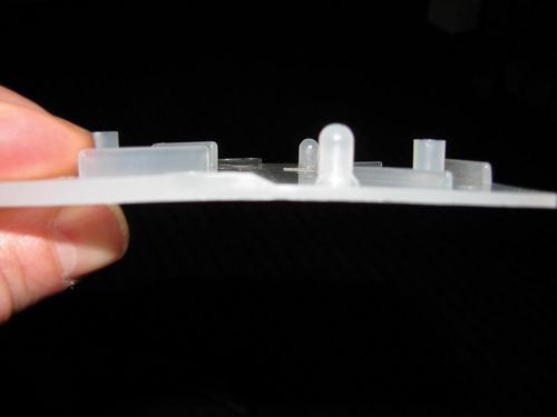
Figure 1 shows a sample block Glenn Beall designed to demonstrate more than 30 common problems in part and tool design, processing, and plastic response to processing. Note that one side of the block is significantly thicker than the other, roughly 0.150 in. vs. 0.075 in. The thick section cools more slowly and shrinks more than the thin section, pulling the thin side down and warping the part. This is with a high-shrink, unfilled, semi-crystalline resin such as polypropylene, polyethylene, or acetal. The warpage would be less with a low-shrink amorphous polymer such as ABS, HIPS, or polycarbonate. The amount of shrinkage is polymer-dependent and proves the need for different rules for allowable nominal-wall variations in different polymers.
Infrared (IR) thermal imaging has great potential as a troubleshooting and inspection tool in plastic processing. In this issue of thick vs. thin nominal wall for part design, IR provides some amazing data. Figure 2 shows the thermal image of “Beall’s Block” about 15 sec after ejection. Note the difference in temperature between the thick section at 238 F and the thin section at 118 F. This picture screams at us to pay attention to keeping the nominal wall uniform. It also clearly demands that the customer pay more for that part. If the part has thick sections, it has to stay in the mold longer to cool, hence there is more machine time—and extra plastic—that have to be paid for.
How can any sane toolmaker, designer, processor, manager, or executive see this picture and expect a flat part? Any attempt to prevent this part from warping with a high-shrink resin would be fighting Mother Nature, and she will beat you every time. The thick section will stay hot longer no matter what the mold is made of or where the cooling lines are. You can try to fixture the part to prevent or minimize warpage. But as Mike Sepe would say, such an approach makes for unhappy molecules, and if you put the part through a thermal cycle or two, it will warp.
This principle can also be translated into tool design. You may have a uniform nominal wall, but if the cooling lines are not properly located you will have differential cooling, resulting in differential shrinkage. Not an easy problem to solve when you have cores forming a barrel or well in your part. It is easy enough to get cooling lines spaced evenly in the cavity, but cooling the core is often difficult and costly. And in most cases the plastic shrinks onto the core and away from the cavity. Thus, the core has to take out more heat. Pay to have the tool built properly.
Make this your molding mantra: All five key components listed above interact. Design must provide a reasonable nominal wall. Different resins have different shrinkage characteristics. Tool design and construction must provide proper and uniform cooling. Processing must properly pack out the part so the part stays in contact with the mold surfaces. And testing must check the part to make sure it will not distort in the application or in shipping.
Folks, let’s get our act together.
About theAuthor
John Bozzelli is the founder of Injection Molding Solutions (Scientific Molding) in Midland, Mich., a provider of training and consulting services to injection molders, including LIMS, and other specialties. E-mail john@scientificmolding.com or visit scientificmolding.com.
Related Content
Using Data to Pinpoint Cosmetic Defect Causes in Injection Molded Parts
Taking a step back and identifying the root cause of a cosmetic flaw can help molders focus on what corrective actions need to be taken.
Read MoreProcess Monitoring or Production Monitoring—Why Not Both?
Molders looking to both monitor an injection molding process effectively and manage production can definitely do both with tools available today, but the question is how best to tackle these twin challenges.
Read MoreIs There a More Accurate Means to Calculate Tonnage?
Molders have long used the projected area of the parts and runner to guesstimate how much tonnage is required to mold a part without flash, but there’s a more precise methodology.
Read MoreWhat to Look for in High-Speed Automation for Pipette Production
Automation is a must-have for molders of pipettes. Make sure your supplier provides assurances of throughput and output, manpower utilization, floor space consumption and payback period.
Read MoreRead Next
People 4.0 – How to Get Buy-In from Your Staff for Industry 4.0 Systems
Implementing a production monitoring system as the foundation of a ‘smart factory’ is about integrating people with new technology as much as it is about integrating machines and computers. Here are tips from a company that has gone through the process.
Read MoreFor PLASTICS' CEO Seaholm, NPE to Shine Light on Sustainability Successes
With advocacy, communication and sustainability as three main pillars, Seaholm leads a trade association to NPE that ‘is more active today than we have ever been.’
Read More
.jpg;width=70;height=70;mode=crop)


