Injection Molding: The Causes of Warpage
Sponsored ContentIdentifying warpage is one of the easiest aspects of injection molding. Understanding the cause is a little more complicated. Here’s a close look at the sources of warpage and how to prevent it.
Share
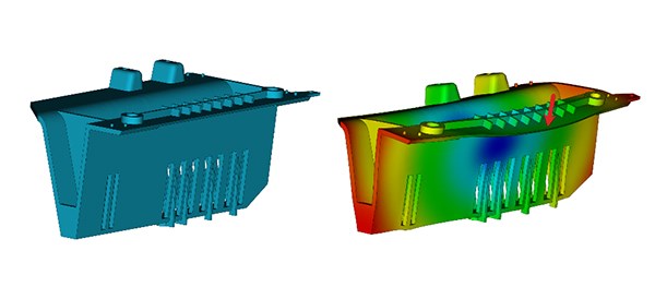
Displayed is a screenshot from Autodesk Moldflow showing a warped injection molded plastic part.
Anyone, including the average consumer, can detect when a part that should be naturally flat is bowed or twisted right after manufacturing. If that warped part was manufactured through plastic injection molding, that means there could have been an opportunity to reduce, or even prevent the unintentional bending.
The first step is to understand why the part is warping, which is a complicated task, but one that’s essential to mitigating the issue. Learning the concepts behind plastic warpage can lead to developing an approach to reduce it. And with the assistance of technology—such as plastic injection molding simulation software Autodesk Moldflow—engineers can validate those solutions before the manufacturer cuts mold steel.
Use Autodesk Moldflow Adviser early in the design process to ensure molding success.
Plastic Shrinkage
Material shrinkage during and after manufacturing plays an important role in why injection molded plastic parts warp. Before we dive into parts warpage, it’s important to understand how and why plastic materials shrink. To do that, we need to start at the molecular level with a close look at what happens when plastics melt and cool. For the most part, the melting and cooling characteristics depend on the type of polymer and whether any filler or fiber reinforcement is present.
1. Amorphous Materials
One polymer type is referred to as amorphous, which includes materials such as ABS, polystyrene, and polycarbonate, among others. They have a random and entangled molecular orientation in their natural state, much like a bowl of spaghetti. As these materials melt, the forces between molecules weaken and they move away from each other. In addition, the shear experienced during the injection phase (which is similar to friction) causes individual molecules to uncoil and align to the direction of flow. When flow stops, the molecules relax and return to a state of random orientation. The intermolecular forces pull them closer together until the temperature drops enough to freeze them in place. These forces result in uniform shrinkage, but the relaxation effect causes more shrinkage in the direction of flow.

2. Semi-crystalline Materials
Unlike amorphous materials, semi-crystalline materials have regions of highly ordered, tightly bundled molecular structures. When they melt, the crystalline structures loosen and the molecules align to the direction of flow, much like amorphous polymers. But when the materials cool, they don’t relax. Instead, they maintain their orientation in the direction of flow and the molecules begin to recrystallize, resulting in significantly higher shrinkage rates. In this case, however, the effect is much greater in the direction perpendicular to flow.

3. Fiber-reinforced Materials
Fibers are often combined into a polymer material to add strength and other properties. When fibers are introduced into the plastic, they may counteract shrinkage effects due to molecular orientation described above. Fibers do not expand or contract as temperature changes, so fiber-filled materials will typically experience reduced shrinkage in the direction of their orientation.

This shows polypropylene tensile bar shrinkage without glass fiber in two gate locations: end of the part (left) and center of the part (right). (Autodesk Moldflow)

This shows polypropylene tensile bar shrinkage with glass fiber in two gate locations: end of the part (left) and center of the part (right). (Autodesk Moldflow)
How Shrinkage Varies
The underlying cause of warpage is deceptively simple: variations in shrinkage. Simply put, if a part shrinks perfectly uniformly in all directions, it becomes smaller but retains the correct shape. If, however, any element of the part shrinks at a different rate than any other element, the difference creates internal stresses. If these stresses exceed the part’s structural integrity, the part will warp when it is ejected from the mold.
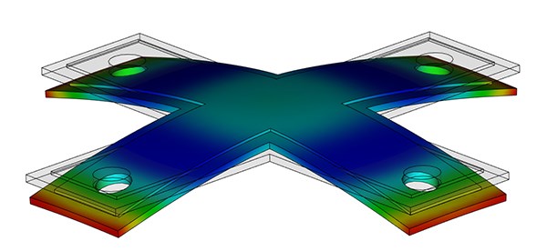
Shrinkage variation of an injection molded part, as simulated within Autodesk Moldflow.
In general, there are four shrinkage variations:
1. Regional
This is when shrinkage rates vary on the part between the regions closest to the gate and regions closest the end of fill (EOF); typically this variance is between the thicker (gate area) and thinner (EOF) areas of the part. One region is essentially shrinking more than another.
2. Through the Thickness
When looking at the cross-section of the part, this shrinkage difference occurs when the shrinkage on the top differs from that of the bottom. This variance can cause the part to bow because one side is able to shrink more and, as a result, will be smaller relative to the other side.
3. Directional
Due to molecular or fiber alignment, differences in shrinkage can occur both parallel to and perpendicular to the material’s orientation, or direction of flow. As mentioned previously, an amorphous material tends to shrink more in the direction parallel to flow. For crystalline materials, shrinkage is usually higher perpendicular to flow.
4. In-plane vs. Thickness
Polymers tend to shrink more in the thickness direction than they do in the plane of the surface. This effect is caused by mold restraint (or lack of mold restraint through the thickness of the part). The difference in shrinkage between the in-plane and thickness directions can cause warpage, particularly in the corners of the part due to these sometimes being thicker than the nominal wall thickness.
Why Variations Happen
While it’s clear that varying shrinkage rates can cause warpage, it’s also important to understand why these differences occur in the first place. Here are five of the most common reasons:
1. Cooling Rates
With any semi-crystalline material, a high cooling rate results in less time for the crystalline structures to form. This effect decreases total volumetric shrinkage. The same effect applies to amorphous materials, but because there is less overall shrinkage the degree to which high cooling rates reduce shrinkage is lessened.
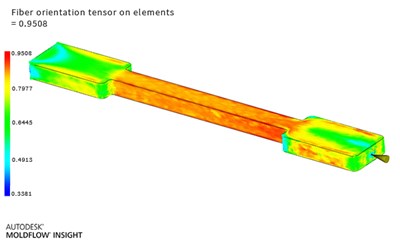
Autodesk Moldflow screenshot showing fiber orientation. Red = fibers are oriented along with flow;
Blue = oriented perpendicular to flow
2. Orientation Due to Filling
Initially, the orientation of long, stringy polymer molecules is caused by shear stress during flow. When the polymer is still at a high temperature and shear stress is removed, the orientation will relax. (Orientation is locked-in only when shearing and freezing occur simultaneously.) When this relaxation occurs in amorphous materials, there is generally more shrinkage parallel to flow. Because the molecules of crystalline materials are aligned in the direction of flow, most crystallization will occur perpendicular to flow, causing more shrinkage in that direction.
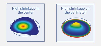
Differential Shrinkage
3. Mold Restraint
While the part is in the mold, it can’t shrink within the plane of its surface—but it can shrink in the direction of its thickness. This has two effects. First, there is more shrinkage in the thickness direction. Second, the polymer accumulates stresses in the plane of its surface. After ejection, these stresses may relax as the part continues to cool, causing warpage. The higher the mold temperature, the lower the cooling rate, and the more stresses relax from the part. Mold restraint is also material dependent. Materials that resist creep (and relax more slowly) have higher linear shrinkage, while materials that relax more quickly have lower linear shrinkage.
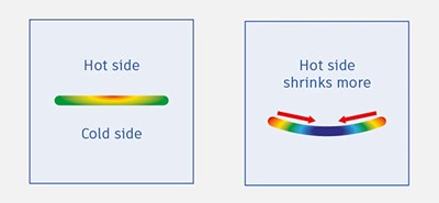
Differential Cooling
4. Temperature Differences Through the Thickness
When the mold temperature on one side of the cross-section is different from the other, shrinkage will not be uniform from side to side. In essence, the plane on one side of the part will shrink more, causing it to be smaller than the other side creating a bending moment that can lead to warpage.
5. Thickness Variations and Uneven Packing
When there are varying thicknesses of the part, thick areas will take longer to cool, which can lead to higher shrinkage. A similar effect occurs with areas that are far from the gate. If a constant packing profile is used, areas closer to the gate will be denser and cool at a different rate than areas further from the gate, causing shrinkage variance.
How Simulation Can Help
Managing warpage is a complicated task, given the number of factors involved and how each one can affect the others. Simulation software can make this work easier by allowing engineers to address the problem earlier in the product design cycle.
Use Autodesk Moldflow to run a cooling analysis in both gas-assisted injection molding and two-shot overmoulding.
Using simulation tools, such as Autodesk Moldflow, allows engineers to set up and run analyses to visualize how much shrinkage and warpage to expect, given the current part material, design, and expected processing conditions. Through the visualization tools, results can be scaled and anchored for easier interpretation and comparison to other simulations.
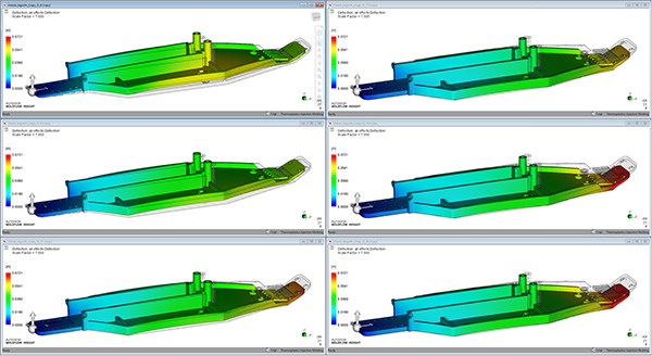
Displayed is a simulation comparing various processing options and their effects on part warpage. (Autodesk Moldflow)
Iterating designs through manual or automated workflows enable engineers to change processing conditions or part design to identify a combination that produces an acceptable part. Moldflow’s automated optimization analyses, provide straightforward feedback on the influence of design, material, and process changes toward part warpage.
Moldflow simulations also make it faster and easier to consider a wider range of potential solutions, such as changing the material or mold cooling, of which is more convenient than dealing with warpage after a part is molded.
Final Thoughts
What makes warpage so difficult to diagnose is that there is very rarely one answer. In most cases, multiple effects may be counteracting or exaggerating each other, making it difficult to isolate each effect’s contribution. Understanding how and why plastic warp gives engineers an edge when analyzing through simulation to develop an appropriate solution that conforms with their budget and schedule.
Learn more about how to Predict and Prevent Warpage and get your Free 30-day Trial of Autodesk Moldflow.
