Is a Gear Pump Right for Your Single-Screw Operation
As with everything else, there are pros and cons, but more of the former. They provide processors higher rates while decreasing the temperature of the extrudate while enabling downgauging.
A gear pump positioned between an extruder and downstream equipment can improve the performance of a line. The advantages include the mitigation of pressure surges and as a result flow surges from the extruder; plus a decrease in the discharge temperature by generating part of the pressure required for the die by the pump, which reducesing resin consumption and enables rate increases.
For example, if the extruder is operating with low-frequency discharge pressure oscillations, the gear pump and control algorithm will provide a nearly constant outlet pressure and flow rate to the downstream equipment such as a die. Stable operations with a gear pump will enables plant personnel to operate at the lower thickness specification limits for sheets or films, and thus reduce the resin consumption per unit of product.
If a gear pump is contributing to the generation of the discharge pressure for the downstream equipment for a single-stage extruder, the metering section of the screw will operate with a higher specific rate compared to a process without a pump. Extruders that operate at a higher specific rate will generally operate at a lower discharge temperature. A gear pump used with a two-stage, vented screw can enable higher operating rates while not causing material to flow out the vent port.
Gear pump-assisted extrusion does have some disadvantages, including higher capital costs and operational complexity for the line. The increased complexity is the control of the process. Here, the rate is set by the speed of the gear pump, as shown by Figure 1. Gear pumps are designed to operate at a specific volumetric rate or cm3/(hr/rpm). The specific volumetric rate or volume per revolution is a design specification for the pump. Setting the speed of the pump and knowing the melt density of the resin sets the rate for the line.
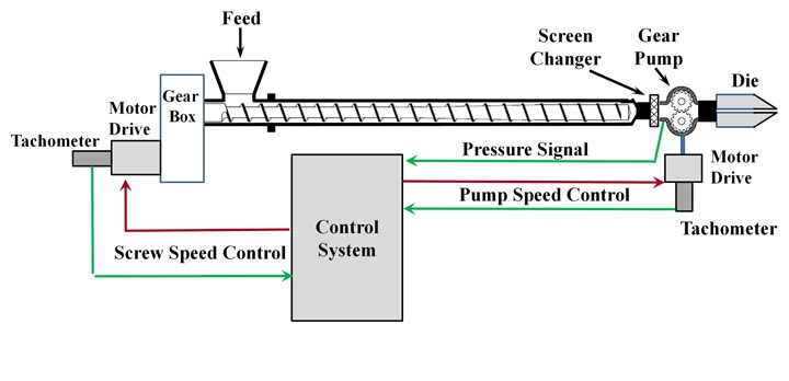
FIG 1 Diagram of a typical gear pump installation for a single-stage extruder and a screen filtering system, showing the rate-controlling scheme. Photo Credit: M. Spalding
To maintain the same rate from the extruder, the controller on the pump adjusts the screw speed to maintain a set point pressure on the inlet side of the pump. The inlet pressure is often referred to as the suction pressure. If the inlet pressure becomes less than the set point pressure, the controller will increase the screw speed.
Gear pumps can enable higher rates for two-stage, vented extruders.
Likewise, if the pressure becomes too high, the controller will decrease the screw speed. For properly designed systems, the screw speed will only have relatively small changes to compensate for slight changes in the pump inlet pressure. But for extrusion processes that are not operating properly and show severe flow surging, the screw speed will have large variations. The discharge pressure from the pump is higher than the inlet pressure and is controlled by the pressure requirements of the downstream equipment.
Gear pumps operate by metering molten resin from the low-pressure inlet side of the pump, and then discharging at a higher pressure to the downstream equipment, as shown by the schematic in Figure 2. The inlet pressure is high enough to force resin in between the gear teeth. As the gears are rotated, the material between the teeth is trapped between the teeth and the body of the pump. At the discharge side of the pump, the intermeshing gears displace the resin and force it out through the discharge flange.
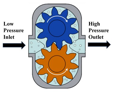
FIG 2 Schematic of a gear pump.
A gear pump is a common method to decrease the discharge pressure from the extruder, especially if the discharge pressure required by the die is relatively high. Decreasing the discharge pressure from the extruder will cause the specific rate to increase and the discharge temperature to decrease for a single-stage extruder, as shown by Figure 3.
For example, a process and die required a pressure of 3,050 psi for operation at a rate of 880 lbs/hr for a high-density polyethylene (HDPE) resin with a melt index of 0.08 dg/min (190oC, 2.16 kg). If all the pressure is provided by a single-stage 4.5 inch diameter extruder (screw design fixed), the discharge temperature will be about 242oC, as shown by the operating curve in Figure 3.
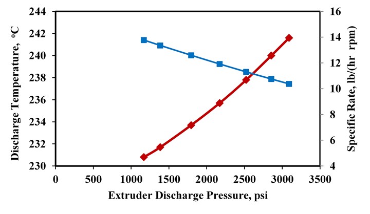
FIG 3 Operation of a 4.5 inch diameter extruder running a HDPE resin at 880 lbs/hr as a function of discharge pressure.
Here, the specific rate for operation is 10.4 lbs/(hr rpm). But if a gear pump is positioned between the extruder and the die such that a portion of the required pressure is generated by the pump, then the specific rate for the screw will increase (causing the screw speed to decrease at a fixed rate) and the discharge temperature will decrease.
If the inlet pressure to the gear pump (discharge pressure from the extruder) was 1,200 psi, the extruder would discharge at 231oC and operate at a specific rate of 13.9 lbs/(hr rpm). Thus, the discharge temperature could be decreased by 11oC and the specific rate increased by 3.5 lbs/(hr rpm), as shown in Figure 3. The axial pressure and temperatures for the two cases are shown schematically by Figure 4.
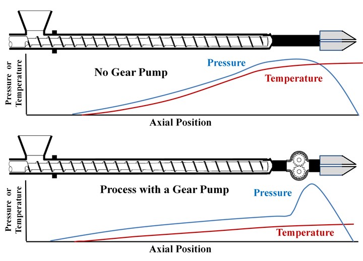
FIG 4 A schematic of the axial pressures and temperatures for processes with and without a gear pump. The rates for both processes are the same, but the discharge temperature for the process with the gear pump is less than that for the standard process.
Higher Throughputs
Gear pumps can enable higher rates for two-stage, vented extruders. A schematic of this process is shown in Figure 5. Because the vent is at atmospheric pressure or under a vacuum, all pressure required to operate the die and screen pack for a system without a gear pump must be generated in the second-stage metering section of the screw. If the pressure required to operate the downstream components is higher than what the second-stage metering channel can develop, then molten resin will flow into the vent port, especially for a poorly designed screw.

FIG 5 Schematic of a two-stage, vented extruder with a downstream gear pump.
A gear pump, however, can enable higher rates while eliminating vent flow by decreasing the discharge pressure of the extruder. For this case, the second-stage metering section only needs to generate enough pressure to operate the pump safely, a pressure typically about 300 to 1200 psi. This pressure level is high enough to keep the pump channels completely full of resin and maintain lubrication in the bearings. The pump will then increase the pressure to a higher level as required by the downstream equipment.
Moreover, if the gear pump is generating most of the pressure required for the downstream equipment, then the screw and extrusion process can be optimized to a lower discharge temperature.
Gear pump-assisted extrusion can provide processors higher rates while decreasing the temperature of the extrudate. Moreover, a gear pump can enable a processor to operate at a lower thickness for sheet or films, reducing the amount of resin in the product, especially for extruders that operate with a minor oscillation in the discharge pressure.
About the Author: Mark A. Spalding is a fellow in Packaging & Specialty Plastics and Hydrocarbons R&D at Dow Inc. in Midland, Michigan. During his 37 years at Dow, he has focused on development, design and troubleshooting of polymer processes, especially in single-screw extrusion. He co-authored Analyzing and Troubleshooting Single-Screw Extruders with Gregory Campbell. Contact: 989-636-9849; maspalding@dow.com; dow.com.
Related Content
Single vs. Twin-Screw Extruders: Why Mixing is Different
There have been many attempts to provide twin-screw-like mixing in singles, but except at very limited outputs none have been adequate. The odds of future success are long due to the inherent differences in the equipment types.
Read MoreMedical Tubing: Use Simulation to Troubleshoot, Optimize Processing & Dies
Extrusion simulations can be useful in anticipating issues and running “what-if” scenarios to size extruders and design dies for extrusion projects. It should be used at early stages of any project to avoid trial and error and remaking tooling.
Read MoreHow to Select the Right Cooling Stack for Sheet
First, remember there is no universal cooling-roll stack. And be sure to take into account the specific heat of the polymer you are processing.
Read MorePart 2 Medical Tubing: Use Simulation to Troubleshoot, Optimize Processing & Dies
Simulation can determine whether a die has regions of low shear rate and shear stress on the metal surface where the polymer would ultimately degrade, and can help processors design dies better suited for their projects.
Read MoreRead Next
Lead the Conversation, Change the Conversation
Coverage of single-use plastics can be both misleading and demoralizing. Here are 10 tips for changing the perception of the plastics industry at your company and in your community.
Read MoreMaking the Circular Economy a Reality
Driven by brand owner demands and new worldwide legislation, the entire supply chain is working toward the shift to circularity, with some evidence the circular economy has already begun.
Read MoreBeyond Prototypes: 8 Ways the Plastics Industry Is Using 3D Printing
Plastics processors are finding applications for 3D printing around the plant and across the supply chain. Here are 8 examples to look for at NPE2024.
Read More


