Overcome the Challenges in Winding Flexible Packaging Film
Not all film webs are created equal. This creates challenges for both winder and operator. Here’s how to handle them.
If all film webs were perfect, then the ability to produce perfect rolls would not be much of a challenge. Unfortunately, due to the natural variation in resins and non-uniformities of the film formation processes, coatings, and printed surfaces, there is no such animal as a perfect film.
With that as a given, the challenge of the winding operation is to ensure that these imperfections do not stand out in appearance and are not amplified during the winding process. Then, the winder operator must make sure that the winding process does not produce additional variations in the product quality. The ultimate challenge is to wind flexible packaging film that will run on a customer’s process without problems and produce high-quality products for their customers.
IMPORTANCE OF ROLL HARDNESS
Roll density, or in-wound tension, is the most important factor in determining the difference between good- and poor-quality film rolls. Rolls that are wound too softly will go “out-of-round” while winding or while being handled or stored. The roundness of rolls is very important in a customer’s operation to enable processing these rolls at maximum production speeds with minimal tension variations.
Tightly wound rolls cause problems of their own. They can create blocking-defect issues where the layers fuse or adhere. When winding extensible film on thin-wall cores, winding hard rolls can cause the cores to collapse. This can cause problems with shaft removal or with inserting the shaft or chucks on the subsequent unwinding operation.
Rolls that are wound too tightly will also exaggerate web defects. Typically, films will have slight high and low areas in the cross-machine profile where the web is thicker or thinner. When winding hard rolls of film, the high-caliper areas build on each other. As hundreds, even thousands of layers are wound, the high areas form ridges, or high spots, in the roll. As the film is stretched over these ridges, it is deformed. Then, when the roll is unwound, these areas produce a defect known as “bagginess” in the film. Hard rolls that have high gauge bands next to low gauge bands will produce a roll defect known as corrugations, or rope marks, in the rolls.
Rolls that are wound too tightly will also exaggerate web defects.
Slight variations in thickness will not be noticeable in a wound roll if sufficient air is wound into the roll in the low areas and the web is not stretched over the high areas. Still, the rolls must be wound hard enough so that they will be round and will stay that way during handling and storage.
RANDOMIZATION OF CROSS-MACHINE VARIATIONS
Some flexible packaging films, either by their extrusion formation process or by their coating and laminating process, have cross-machine thickness variations that are too severe to be wound without exaggerating these defects. To randomize cross-machine variations in the wound rolls either the web or the slitters and winder are moved back and forth relative to the web as they are being slit and wound. This cross machine movement is called oscillation.
For successful oscillation the speed must be fast enough to randomize thickness variations and slow enough that it does not strain or wrinkle the film. The rule of thumb for the maximum oscillation speed is 25 mm (1 in.)/min per 150 m/min (500 ft/min) of winding speed. Ideally the oscillation speed varies proportional to the winding speed.
PROFILING ROLL HARDNESS
As a roll of flexible packaging film material winds, in-wound tension or residual stress builds inside the roll. If this stress becomes greater during winding, the inner wraps towards the core will be put under high compressive loads. This is what causes a defect known as “buckling” of the webs in localized areas in the roll. When winding non-elastic and high-slip films, the inner layers will loosen; this can cause the roll to dish while winding, or telescope when unwinding. To prevent this, the rolls need to be wound tight at the core and then wound with less tightness as the roll builds in diameter.
This is commonly referred to as roll-hardness taper. The larger the finished wound roll’s diameter, the more critical the roll-hardness tapering profile becomes. The secret to building a good roll-hardness structure is to start out with a good solid foundation and then to wind with progressively less in-wound tension.
The larger the finished wound roll’s diameter, the more critical the roll-hardness tapering profile becomes.
The good solid foundation requires starting the winding operation on a high-quality, properly stored core. Most rolls of film materials are wound on paper cores. The paper cores must be of sufficient strength that they can withstand the in-wound compressive tension caused by the film being wound tightly on the core. Typically paper cores are kiln dried to 6-8% moisture. If these cores are stored in a high-moisture environment, they will absorb this moisture and swell to a larger diameter. Then, after the winding operation, these cores can dry to a lower moisture level and will shrink in size. When this happens, the solid wound roll’s foundation will be lost! This causes these rolls to have defects such as buckling, staring and/or telescoping when they are handled or unwound.
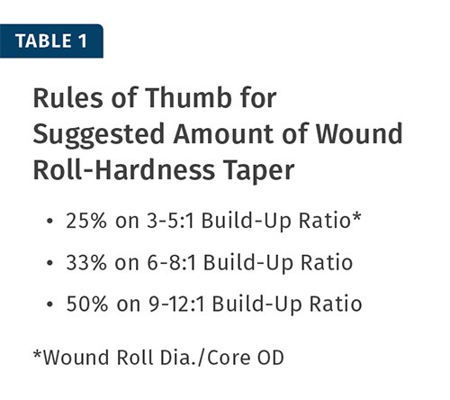
The next step in obtaining the necessary good winding foundation is to start winding with as much roll hardness as possible. Then, as the rolls of film material are wound, the roll hardness needs to be uniformly decreased. The suggested decrease in roll hardness at the finished diameter is generally between 25% and 50% of the starting hardness measured at the core.
The amount of starting roll hardness and the amount of taper of in-wound tension is generally a function of the Build-up Ratio of the wound roll. The Build-up Ratio is the ratio of the core’s Outside Diameter (OD) and the wound roll’s finished diameter. The larger the roll’s final wound diameter (the taller the structure) the more important starting on a good solid foundation and winding a progressively softer roll becomes. Table 1 gives a rule of thumb for the suggested amount of hardness taper based on the Build-up Ratio.
The winding tools to develop roll hardness are web tension, nip pressure (from a pressure or lay-on roll or winding drum) and winding torque from a center drive when center/surface winding film webs. These so-called TNT winding principles were discussed in an article in Plastics Technology’s January 2013 issue. The following describes how each of these tools are used to develop hardness, and offers rules of thumb for starting values to produce the required roll hardness of different flexible packaging materials.
Web-Tension Principle of Winding. When winding elastic films, web tension is the dominant principle of winding used to control roll hardness. The more the film is stretched before winding, the harder the wound rolls will be. The challenge is to be sure that the amount of web tension does not induce significant permanent stresses in the film.
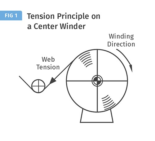
When winding film on a pure center winder as shown in Fig. 1, the web tension is produced by the winding torque from a center drive. The web tension is set for the desired roll hardness at the start and then tapered as the film winds. The web’s winding tension produced from the center drive is typically closed-loop controlled with feedback by tension-measuring transducers.
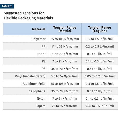
The amount of starting and finishing web tension for a specific material often must be determined empirically. A good rule of thumb for the range of web tension is between 10% and 25% of the film’s elastic limit. Many published papers suggest amounts of web tension to be used for specific web materials. Table 2 lists suggested tensions for many web materials used in flexible packaging.
For winding on pure center winders, the starting tension should be towards the higher value of the suggested tension range. Then smoothly taper the winding tension towards the lower suggested range given in this table.
The amount of starting and finishing web tension for a specific material often must be determined empirically.
When winding a laminated web of several different materials, to obtain the suggested maximum web tensions for laminated structures, simply add the maximum web tensions for each of the materials that have been laminated together (usually disregarding any coatings or adhesives) and apply the sum of these tensions as the maximum web tension for the laminate.
The important tension consideration for laminating flexible film composites is that the individual webs need to be tensioned before they are laminated so that the strain (elongation of the web due to web tension) will be approximately equal for each web.
If one web is strained significantly more than the other web(s), curl problems or delamination wrinkling known as “tunneling” can occur in the laminated webs. The amount of tension should be a ratio of the modulus and the web thickness to prevent curl and/or tunneling after the lamination process.
Nip Principle of Winding. When winding inelastic films, nip and torque are the dominant principles of winding used to control roll hardness. The nip controls the roll hardness by removing the boundary layer of air following the web into the winding roll. The rolling nip also induces in-wound tension into the roll. The harder the nip, the harder the winding roll will be. The challenge for winding flexible packaging film is to have sufficient nip pressure to remove the air and wind hard, straight rolls without winding in too much in-wound tension in order to prevent roll blocking or deforming the web over the high-caliper area.
The nip loading is less material dependent than web tension and will vary greatly with the material and the amount of roll hardness required. To prevent nip-induced wrinkling of the winding film, the amount of nip load is the minimum required to prevent air from winding into the roll. This nip load is often held constant on center winders, as Mother Nature provides the nip-pressure taper with a constant nip-loading force. As the rolls build larger in diameter, the footprint (area) of the nip between the winding roll and the pressure roll becomes greater. If the width of this footprint goes from 6 mm (0.25 in.) at the core to 12 mm (0.5 in.) at a full roll, then the winding nip pressure automatically tapers by 50%. Also, the amount of air following the roll’s surface increases as the winder roll’s diameter increases. This boundary layer of air increases the hydraulic pressure trying to open the nip. This increasing pressure adds nip-load tapering as diameter builds.
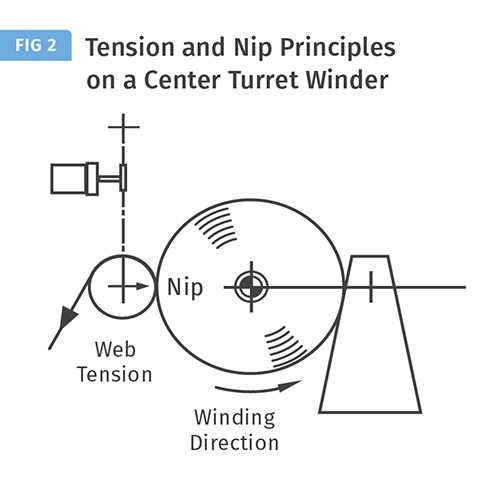
On wide, fast winders used to wind large-diameter rolls, the nip loading may have to be increased as the roll winds to prevent air from winding into the roll. Figure 2 shows a center film winder with an air-loaded pressure roll, which uses both the tension and nip tools to control the winding roll’s hardness.
Sometimes Air Is Our Friend. Some films, especially “sticky” high-friction-coefficient films with uniformity problems need to be gap wound. Gap winding allows a small amount of air to be wound into the roll to prevent web blocking problems inside the rolls and to help prevent deforming webs that have high-caliper bands. To successfully gap wind these films, the winding operation must have the ability to maintain a small constant gap between the pressure roll and the winding material. This small controlled gap helps meter the air being wound into the roll and also directs the web squarely into the winding roll to help prevent wrinkling defects.
Torque Winding Principle. The torque tool to obtain roll hardness is the force induced through the center of the winding roll. This force is transmitted through the web layers, where it cinches or tightens the inner wraps of film. As stated earlier, this torque is used to produce the web tension on center winders. With these types of winders, web tension and torque are the same winding principle.
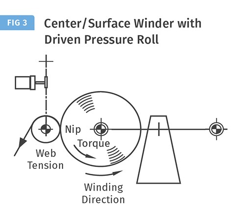
When winding film products on a center/surface type winder, the pressure roll is driven to control the web’s tension, as shown in Fig. 3. The web tension coming into the winder is independent of the winding tension produced from this torque. The incoming web tension in normally held constant for a constant amount of strain in the web coming into the winder.
Center/surface winding should be used when slitting and winding films or other materials with large Poisson’s Ratios, which will change in width with changes in web tension
When winding film products on a center/surface type winder, the control of the winding tension is open-loop controlled. Typically the winding tension starts at 25-50% greater than the incoming web tension. Then this winding tension is tapered as the roll builds in diameter to a value at or even less than the incoming web tension. The pressure roll’s surface drive will regenerate or pull negative (braking) torque when the winding tension is greater than the incoming web tension. As the winding roll’s diameter increases, the surface drive will gradually provide less braking until it reaches zero torque; then winding tension equals web tension. If the winding tension is programmed to go below the incoming web tension, then the surface drive will pull positive torque to make up the difference between the lower winding tension and the higher web tension.
Center/surface winding should be used when slitting and winding films or other materials with large Poisson’s Ratios, which will change in width with changes in web tension. Center/surface winders keep the slit roll’s width constant as constant web tension is brought to the winder. The roll’s hardness will be profiled from the center torque without producing neck-in width problems.
FILM COF PROPERTIES EFFECT ON WINDING
The film’s layer-to-layer coefficient of friction (COF) properties have a major effect on the ability to apply the TNT principles to produce the desired roll hardness without roll defects. In general, films with a layer-to-layer COF value of 0.2 to 0.7 will wind well. However, winding defect-free rolls of high- or low-slip (low- or high-COF) films usually presents major winding challenges.
High-slip films have low layer-to-layer COF (generally below 0.2). These films will often have inner web-slippage or cinching problems when they are winding and/or in subsequent unwinding operations, or will have roll-handling problems in between these operations. This inner web slippage can result in defects such as web scratching, dishing, telescoping, and/or starring roll defects. Low COF films need to be wound as tight as possible at the core with high torque. Then the winding tension produced by this torque is tapered to a minimum amount at three to four times the core OD, and the desired roll hardness is obtained using the nip-winding principle. Air is never our friend when winding high-slip films. These films always need to be wound with sufficient nip loading to prevent air from entering the roll during the winding process.
Low-slip films have high layer-to-layer COF (generally above 0.7). These films will often have blocking and/or wrinkling problems. When winding high-COF films, out-of-round rolls can be experienced at low winding speeds and roll bouncing can be a problem when winding at higher speeds. These rolls can have bump or ripple defects commonly called slip knots or slip wrinkles. High-COF films are best gap wound with a minimum gap between the following roll and the winding roll. Spreading needs to be provided as close to the winding point as possible. A FlexSpreader covering on a well-wrapped idler roll just before the winder has helped to minimize slip wrinkle defects in high-COF winding applications.
LEARN MORE
This article has presented a number of roll defects caused by improper roll hardness. The challenge of identifying and eliminating these and other roll and web defects has been made easier by a new reference book, The Ultimate Roll and Web Defect Troubleshooting Guide. This book is the updated and expanded version of TAPPI Press’s best-seller, Roll and Web Defect Terminology.
The expanded version was written and edited by 22 industry experts with more than 500 years of combined experience in web handling and winding. It’s available through TAPPI; click here here.
Related Content
Why Are There No 'Universal' Screws for All Polymers?
There’s a simple answer: Because all plastics are not the same.
Read MorePart 2 Medical Tubing: Use Simulation to Troubleshoot, Optimize Processing & Dies
Simulation can determine whether a die has regions of low shear rate and shear stress on the metal surface where the polymer would ultimately degrade, and can help processors design dies better suited for their projects.
Read MoreHow to Select the Right Cooling Stack for Sheet
First, remember there is no universal cooling-roll stack. And be sure to take into account the specific heat of the polymer you are processing.
Read MoreWhat to Know About Your Materials When Choosing a Feeder
Feeder performance is crucial to operating extrusion and compounding lines. And consistent, reliable feeding depends in large part on selecting a feeder compatible with the materials and additives you intend to process. Follow these tips to analyze your feeder requirements.
Read MoreRead Next
Which Winder’s for You?
It's time to apply more science to the process of selecting the right kind of winder for your operation.
Read MoreGet Rid of Wrinkles In Blown Film
The biggest cause of wrinkles in the blown film process is instability of the bubble between the air ring and where the bubble reaches full diameter.
Read MoreDon’t Wind Wrinkles Into Your Film
Wrinkles are a major cause of defects in extrusion winding and converting, especially with thinner films, which are much more wrinkle-prone than thick ones. The cause of most wrinkles is located close to the roller where the wrinkle first appears and can be identified by looking at the orientation and pattern of the wrinkle. First, find the cause; then try to eliminate or at least reduce it.
Read More
