Robot End-of-Arm Tooling: Making a Big Difference
Often overlooked as a small part of an automation system, clever end-of-arm tooling techniques and designs can improve part quality, heighten efficiency, and eliminate headaches for any molder.
It happens all the time: Molders will have a supremely curable problem with their automation process, but simply overlook it because they were unaware there was a solution out there. End-of-arm tooling (EOAT) is an underutilized part of the automation process. It is too often seen as a standard vacuum cup, assumed to be the lone method to pick parts from the mold. And if the cup is unsuitable for whatever reason, dropping the parts directly from the mold is the only other option. This is simply not true. Many issues with molder automation can be solved through unique EOAT beyond the vacuum cup.
This article will highlight common difficult parts or part-removal circumstances encountered by molders and some of the creative designs and techniques they can use at the end of the robot to make nearly every application both less costly and more efficient with higher quality parts.
HIGH-CAVITATION MOLDS
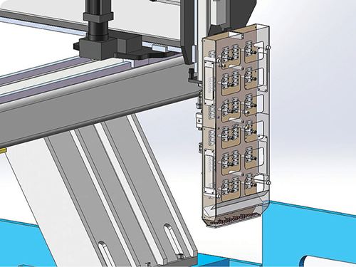
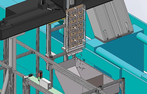
Normally for a high-cavity mold—i.e., 128, 256, or 512 cavities—there are simply too many contact points for a standard EOAT to collect the parts. As a result, most molders will simply eject the parts from the mold, let them fall, and use downstream automation to handle them farther on. This can cause numerous issues, including contamination, part damage, part loss, and increased costs.
A simple way to fix this problem is box tooling. An end-of-arm “shoebox” will press against the face of the mold, making clean contact to guarantee that when the parts eject they are 100% contained. The box collects the parts in the bottom and then can gently release them wherever they need to go. It helps keep parts from getting damaged or scattered, and allows for more efficient movement of the molded parts to the next phase of the automation process.
MICRO PARTS
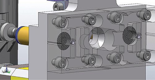
Micromolding is becoming increasingly popular, and handling the microscopic parts has been a challenge for many molders new to the process. The parts are so small that they can be easily lost if they were simply ejected, or they can be sucked into standard vacuum tooling and cause significant issues. Generally, they are too small for a gripper to get hold of.
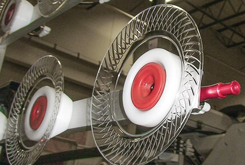
One solution to this is to add EOAT with a vacuum mesh pocket. The mesh is custom-made for the part to guarantee that it will not be sucked into the vacuum. The tooling is placed up to the mold and the vacuum pulls the part against the mesh and pulls it away safely and securely without danger of part loss or damage.
An alternative sometimes used is EOAT that does not grip the parts at all. Rather, it consists of vacuum openings that line up with each mold cavity, backed by flexible tubes attached to the EOAT, which suck parts down into receptacles separated by cavity.
BOX OR TRAY PLACEMENT
Many times a molding process ends with the parts in a tray or a box. This is sometimes accomplished with an excessive amount of downstream automation and conveying systems that add cost and increase the possibility for failure and mistakes in the production stream. Tightly packing parts into their packaging is one of the more common headaches we find in the industry.
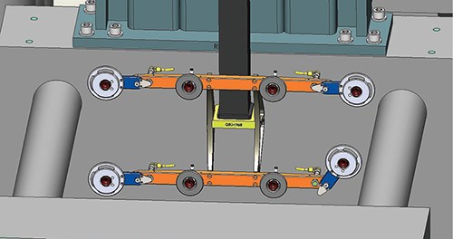
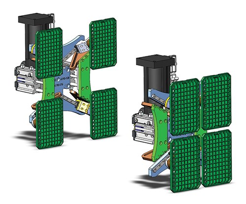
A way to simplify this problem with automation is to use a pitch-revising EOAT. As parts are never molded directly next to one another, the tool needs the ability to collapse, in one or two directions, from an arrangement matching the cavity spacing into a formation that will match the tray or box spacing that the part will end up in. Such tooling will manipulate itself to match the pitch of the box or tray, with the added capability to place the parts into different pockets.
TIGHT SPACES FOR ROBOTS
Sometimes molders have to squeeze oversized molds in their machines. These molds have to be installed in pieces, and parts may barely clear the tiebars during extraction. A resulting issue is that robots have very little room for deviation from their programmed path, and even a centimeter or two off will create a crash. Crashes can be disastrous and expensive, causing severe damage to both the robot and the machine involved.
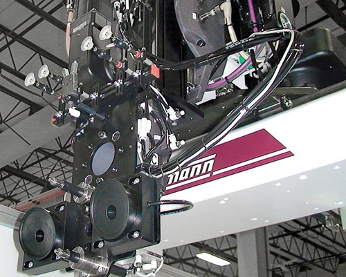
One solution to this is the use of breakaway arms on the EOAT. If the robot is operating close to the tiebars, this tooling will work as an effective safety measure against any potential crashes. Instead of breaking, the arm will collapse with the pressure and force and stop the robot to prevent any further damage.
There are a few ways to execute this, but one effective way is to use plastic screws in place of metal ones. The plastic screw changes the crash force, breaking with less pressure than would damage the machine and requiring a comparatively minor fix to what would otherwise be extremely costly in terms of both repairs and downtime. Another way is the use metal ball detents that will allow a pivot and then will easily snap back into place. Sensors are used to detect these breakaways and stop the robot.
LARGE, AWKWARD PARTS
With some larger or awkwardly shaped parts, a vacuum cup cannot get a solid hold and the part wobbles while being moved. One example of this would be for plates. The vacuum cup can hold only a small part of the plate in the center, and the plate will flop around while being moved to the stacking phase. This leads to premature wear on the cup and difficulty stacking.
To stop this movement of the part and minimize wear on the EOAT, use a bellows cup. This different design, essentially a standard vacuum cup with folds in it and a solid piece behind the cup, allows for much firmer control. The cup will then have a spring effect as it pulls the part in, allowing for more contact points for stability. Once it has been pulled against the solid piece, it will create a stable hold on the part, allowing for firm control throughout the moving and stacking process.
POROUS PARTS
With a porous part, one that is textured or contains holes, a standard vacuum cup will not usually work. The holes or the texture on the molded piece make it difficult to create the vacuum necessary to get a firm grip on the part. As a result, these parts are often free-dropped instead of being picked and placed, which leads to part damage and unorganized automation.
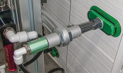
One EOAT solution is to superpower the airflow. With a strong enough vacuum, it can compensate for the air loss through the holes in the part. To do this, a standard vacuum won’t work. Instead, install a high-flow vacuum circuit to increase suction. Then install the vacuum generator directly onto the EOAT and plumb down a large airline from the circuit. This will create a large, oversized vacuum right on the back of your tooling and create the necessary vacuum pressure to grab almost any part.
INSERT MOLDING
Insert molding requires perhaps the most critical alignment of any molding process because there are more steps in the process. For this reason, and because of the added cost of scrap containing inserts, molders want to be as confident as possible that their pieces are being molded exactly the right way every time. This means both that the molding process must be as consistent as possible, and also that a quick and easy quality control should exist for peace of mind.
Two EOAT techniques can be used to help this process. The first is docking. Inserts must be placed in the mold as accurately as possible. To minimize a very time-consuming realignment after a mold change, docking is highly recommended. It is a simple male/female pin on the robot and the mold that registers the robot arm every time so the molder can be assured it is in the right place. With positive registration on each shot, consistent positioning and an accurate grab is guaranteed with this very basic technique.
For quality control of a part with a metal insert, you can place a metal detector right on the EOAT. A probe with a sensor goes up to each part and verifies that the metal piece was correctly molded in. This is another relatively simple solution that allows for quick and easy quality control right at the molding point as opposed to farther downstream.
Related Content
Ultrasonic Welding: Tips, Techniques, and Troubleshooting
In this collection of content, we provide expert advice on welding from some of the leading authorities in the field, with tips on such matters as controls, as well as insights on how to solve common problems in welding.
Read MoreThe Importance of Barrel Heat and Melt Temperature
Barrel temperature may impact melting in the case of very small extruders running very slowly. Otherwise, melting is mainly the result of shear heating of the polymer.
Read MoreGot Streaks or Black Specs? Here’s How to Find and Fix Them
Determining the source of streaking or contamination in your molded parts is a critical step in perfecting your purging procedures ultimately saving you time and money.
Read MoreMedical Tubing: Use Simulation to Troubleshoot, Optimize Processing & Dies
Extrusion simulations can be useful in anticipating issues and running “what-if” scenarios to size extruders and design dies for extrusion projects. It should be used at early stages of any project to avoid trial and error and remaking tooling.
Read MoreRead Next
For PLASTICS' CEO Seaholm, NPE to Shine Light on Sustainability Successes
With advocacy, communication and sustainability as three main pillars, Seaholm leads a trade association to NPE that ‘is more active today than we have ever been.’
Read MoreMaking the Circular Economy a Reality
Driven by brand owner demands and new worldwide legislation, the entire supply chain is working toward the shift to circularity, with some evidence the circular economy has already begun.
Read MoreBeyond Prototypes: 8 Ways the Plastics Industry Is Using 3D Printing
Plastics processors are finding applications for 3D printing around the plant and across the supply chain. Here are 8 examples to look for at NPE2024.
Read More
