Switch Over To Consistent Quality
A new process-control method picks up variations in melt quality and viscosity during the injection phase and equalizes them within the same shot.
Although modern electric injection units can execute movements with the highest levels of repeatability, consistent molded part quality is still often unachievable in practice. The most important factors influencing this have been found to be variations in the quantity of melt and melt viscosity. A new process-control method picks up these variations during the injection phase and equalizes them within the same shot.
How stable is the cushion on machine X? How strongly does the peak value of the injection pressure vary on machine Y? Injection molding machine manufacturers are often confronted by questions like these. Since these parameters, for the most part, depend less on the machine than on the process as a whole (material, mold, drying, process settings, etc.), it is very difficult to provide a blanket answer to such questions. It is important, therefore, to first look in more detail at why repeatable movements in the injection molding machine do not necessarily lead to consistent molded part quality.
For this analysis, an LCD frame was molded in polypropylene on an all-electric Engel e-mac 200/50. In order to be able to isolate the variations in the filling phase, short shots were produced without holding pressure. Screw movement was stopped at a defined switchover position representing a fill level of about 95%. In doing this, the smoothing effect of the holding phase was removed and deviations in injection could be assessed directly on the basis of the fill level and weight of the molded part.
External inductive position transducers recorded variations in the injection start and end positions. Encoders integrated into the electric drives ensured a high level of positional accuracy so that the start position of the screw was repeatable to within ±10 μm and the end position to within ±3 μm. For the 25-mm diam. screw, these values equate to a maximum variation in volume of 0.012 cm³, which for polypropylene is equal to a weight variation of 0.009 g.
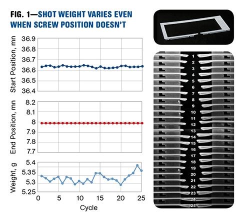
However, the shot-weight variations actually measured during testing were 0.11 g, which is 12 times as much as could be explained by the tiny variations in screw position (Fig. 1). Why does the amount of material vary so much, despite the high precision of the movements? Initial suspicions centered on the closing behavior of the non-return valve. Yet, in many cases this is found to be no more than prejudice. Detailed investigations have shown another important effect: At the end of decompression after plasticating, melt continues to flow from the screw channels into the space in front of the screw that is at a lower pressure. Due to slightly different boundary conditions (material homogeneity, melt temperature, viscosity, etc.), the quantity of melt flow changes, as can be clearly observed in the molded parts.
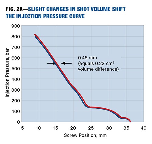
Finally, whether variations in the quantity of melt are caused by continuing polymer flow or by leakage losses during the closing of the non-return valve, the effect is the same: During injection, the curve of specific injection pressure is shifted (Fig. 2A). The different filling levels lead to different pressure values at the switchover point.
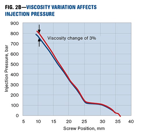
A second significant reason for the process variations are changes in polymer viscosity that are mostly based on batch or moisture variations. Fundamentally, the pressure required to fill the mold is proportional to melt viscosity. If the viscosity increases, the pressure during injection rises more steeply (Fig. 2B).
WHAT SWITCHOVER TYPE WORKS BEST?
With position-dependent switchover, the process is fairly sensitive to variations in melt quantity. Switchover at a fixed point is, strictly speaking, only optimal for constant material quantity—i.e., if exactly the same amount of polymer melt continues to flow and no leakage occurs during closure of the nonreturn valve. Unfortunately in practice this is rarely the case. Pressure-dependent switchover can provide a quick fix. If the pressure rises earlier due to a higher amount of melt, the set switchover pressure will be reached earlier. In this way, variations in fill level can be avoided.
However, this delivers satisfactory results only as long as melt viscosity remains constant. With increasing viscosity the set switchover pressure will be reached too early. Since the melt front will not have reached the desired filling level, variations in the molded part result. This means that where variations in viscosity are the principal problem, position-dependent switchover is the preferred choice. A constant quantity of melt would be injected, independent of the pressure profile, at least in theory, if it were not for the previously mentioned variations in shot volume.
Time for an interim conclusion: If variations occur only in the melt quantity, then pressure-dependent switchover is the best option. If only the melt viscosity varies, then position-dependent switchover works better. The dilemma for the injection molder is that under real production conditions, both types of variation occur at the same time. Regardless of which switchover type is chosen, sooner or later it is almost certainly the wrong one.
A DIFFERENT WAY TO SWITCH OVER
Is it better to switch on pressure or position? This has been one of the eternal questions for injection molders. Actually, what they really want to do is to switch over at a particular filling level in the cavity. It is precisely that—and quite a bit more—that is possible using “iQ weight control,” a new process-control method developed and patented by Engel.
The iQ weight-control software (integrated into Engel CC 200 and CC 300 control systems) analyzes the injection pressure as a function of screw position, in real time during the injection phase, and compares this to a reference cycle. The algorithm differentiates between three types of variation:
•A shift of the pressure curve in the x-direction (Fig. 2A);
•Changes in the slope of the pressure rise (Fig. 2B);
•Variations that cannot be explained by either of the above.
Based on these variations, three meaningful new process parameters are created:
1. Injection volume: This is the measure of material actually injected after taking melt-quantity variations into account.
2. Viscosity change: This reflects changes in the melt viscosity as a result of batch, moisture, or temperature variations.
3. Compliance of the pressure curve: This parameter shows whether the pressure curve has changed fundamentally in comparison to the reference cycle (examples: cold slugs, blocked cavity, etc.).
These parameters can be used for comprehensive monitoring of the injection process and to compensate for variations that are detected. Regardless of whether position- or pressure-dependent switchover was selected, the injection-speed profile and switchover point are altered during the injection process so that the changeover to holding pressure takes place at the same filling level and volume flow as in the reference cycle. The initial conditions for the holding phase then only show minimal variation, and the repeatability of the process and part weight are clearly improved.
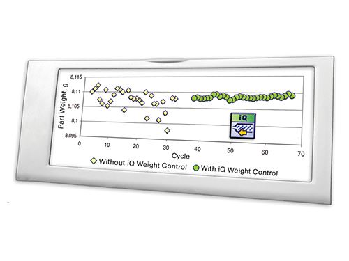
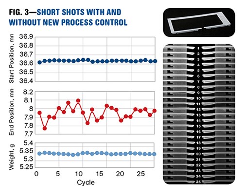
For example, if the iQ weight-control system is activated during production of the previously mentioned LCD frame, this results in the position and weight values shown in Fig. 3. Since the end position of the screw is now actively changed, it obviously varies more in comparison to the trials without process control (Fig. 1). In this case, the high precision of the screw-positioning system is absolutely necessary in order to execute exactly the desired compensation through a deliberate change in the switchover point. The results speak for themselves: The range of variation in the part weight is reduced from 0.113 g to 0.016 g.
BETTER REPRODUCIBILITY
Even when the LCD frame is completely filled, the potential of this new method can still be seen. It is of particular interest for components with a high ratio of flow length to wall thickness (for the LCD frame this is much more than 200:1). In such cases the filling phase is principally responsible for determining molded part properties, and the holding phase can compensate only to a limited degree.
When injecting this LCD frame mold with acetal (POM), the conditions are even more difficult than for PP. Filling the mold 100% requires an injection pressure of more than 2000 bar. Even without process control, the range of variation was comparatively small at 0.014 g (0.177%). However, with the new software this could be reduced to a remarkable 0.002 g (0.025%), an improvement of 86% (see image on p. 30).
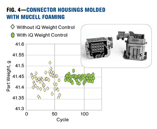
There are even some special processes where a holding pressure is not used or kept very short—in these cases, the example used here of partial filling without holding pressure can have real relevance. Such cases include physical foaming (like the MuCell process from Trexel), injection-compression molding, and gas-assist or water-injection technology. FCI Austria GmbH in Mattighofen, Austria, is one of the first companies to test iQ weight control in production conditions. Connector housings of 30% glass-filled PBT were molded in two cavities using MuCell physical foaming on a tiebarless hybrid Engel e-victory 310/90. The MuCell process works without holding pressure since the foam expansion compensates for shrinkage. At the end of the filling phase the shutoff nozzle is closed and therefore the part weight is determined by the injection process alone. In this case, iQ process control reduced weight variation by 67% (Fig. 4).
The change in flow behavior caused by incorporating a gas like nitrogen in the melt during foam injection molding can also be quantified by iQ weight control. In the given example, the viscosity decreased by about 7%.
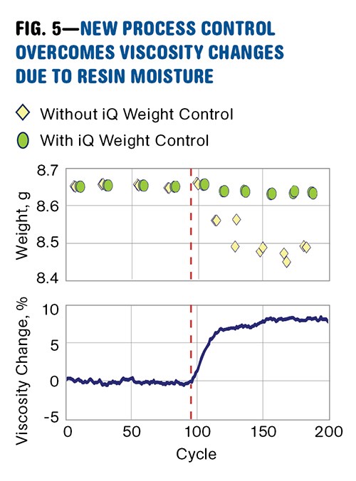
With polymers that require intensive pre-drying, the viscosity can vary over long periods of time due to variations in moisture content. Data from the production of a keyboard from nylon shows how the change from a 9:1 mixture of dried and undried material to 100% dried leads to an increase in viscosity of about 8% (Fig. 5). Without the control system, short shots were produced after the moisture change, while with iQ weight control the part weight remained stable.
Precise movements by the machine are necessary, but not in themselves sufficient for consistent product quality. The widely used monitoring of screw position can deliver only a limited assessment of part quality. For example, a varying material cushion can just as easily mean that variations during the injection phase were compensated during the holding phase.
As a result, the iQ weight-control system takes a new approach. Essential process parameters are derived from the screw-position and injection-pressure curves. This takes a step away from monitoring purely machine-based variables and towards the actual process and the associated part quality.
Based on the process-oriented parameters, the new system can automatically compensate for short- and long-term quality deviations, resulting in a sustained improvement in repeatability. Frequent adjustments to process parameters due to changes in environmental and material conditions belong in the past.
Related Content
Process Monitoring or Production Monitoring—Why Not Both?
Molders looking to both monitor an injection molding process effectively and manage production can definitely do both with tools available today, but the question is how best to tackle these twin challenges.
Read MoreBack to Basics on Mold Venting (Part 1)
Here’s what you need to know to improve the quality of your parts and to protect your molds.
Read MoreThree Key Decisions for an Optimal Ejection System
When determining the best ejection option for a tool, molders must consider the ejector’s surface area, location and style.
Read MoreKnow Your Options in Injection Machine Nozzles
Improvements in nozzle design in recent years overcome some of the limitations of previous filter, mixing, and shut-off nozzles.
Read MoreRead Next
For PLASTICS' CEO Seaholm, NPE to Shine Light on Sustainability Successes
With advocacy, communication and sustainability as three main pillars, Seaholm leads a trade association to NPE that ‘is more active today than we have ever been.’
Read MoreSee Recyclers Close the Loop on Trade Show Production Scrap at NPE2024
A collaboration between show organizer PLASTICS, recycler CPR and size reduction experts WEIMA and Conair recovered and recycled all production scrap at NPE2024.
Read MoreBeyond Prototypes: 8 Ways the Plastics Industry Is Using 3D Printing
Plastics processors are finding applications for 3D printing around the plant and across the supply chain. Here are 8 examples to look for at NPE2024.
Read More
