Tooling: Hot Sprues—Mold a Disk or Not?
Having a hot sprue shut off against the parting line versus intentionally molding a thin disk has been the subject of controversy for many years.
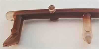
A difference of opinion regarding a particular mold-design preference came up again recently. The conundrum was whether to intentionally leave a space or gap between the end of a hot sprue and the parting line of a cold-runner, two-plate mold. I’m not talking about the space required to compensate for linear thermal expansion. I’m referring to an additional space to mold a thin disk of plastic, about 0.005 to 0.050 in. thick, between the two surfaces.
I decided it was time to see if I could get some closure on the matter—or at least present all the arguments for and against, so that mold designers can make an informed decision about which option suits their needs or application best. Not surprisingly, I couldn’t find a single word about this subject on the internet, nor in any of the plastics reference books, seminar handouts, or magazine articles I have collected over the years. So I reached out to several well-respected hot-sprue manufacturers, tool makers, processors and materials company technical representatives for their thoughts. I was amazed how their steadfast opinions on the preferred design, as well as their reasons, varied from one extreme to the other.
Hot Sprues: Mold a Disk or Not?
Probably the best argument for leaving a gap and molding a thin disk is that it guarantees the hot sprue will never extend beyond the parting line of the fixed half of the mold. If it did, the face of the hot sprue would quickly hob the moving side. It was also reported that if the tip extends too far, the repetitive impact against the moving half of the mold can cause the tip to slowly unscrew—making the damage that much more severe and often cause the tip to crack near the notch-sensitive threads. That makes sense, considering the threads of a hot-sprue tip are coated with an anti-seize lubricant, as opposed to an anaerobic adhesive, such as Loctite. Those are both very good reasons for wanting to mold a disk.
Several people said they like the molded disk because it acts as a cold well to catch any solidified material residing in the gate of the hot sprue. I don’t agree. Plastic flows in the path of least resistance.
Unless the disk is very thick, or the material has a very low viscosity, the initial flow of material is going to go right into the wide-open runner—not into a thin disk. In fact, the disk is probably not going to even fill out until the material flow reaches the restrictive gates and the pressure starts to build. Therefore, it’s highly unlikely that a molded disk acts as an effective cold well.
However, a disk will function as a “flash trap.” That is a thin web of material, usually added down the sides of a runner to prevent flashing. The thin web solidifies prior to the melt-delivery system reaching significant pressure. Therefore, a thin molded disk will help prevent the surrounding area from getting damaged by flash. Another good reason for molding a disk.
One argument against molding a disk is the increased chance of the injection pressure causing the hot sprue to “blow back.” Most hot sprues have a standard 1-in. diam. If the peak injection pressure was, for the sake of argument, 14,000 psi of plastic pressure, there will be 11,000 psi trying to push the hot sprue toward the fixed platen. If the molding machine is small and has an associated small amount of nozzle-touch force, there’s a chance the hot sprue will in fact blow back. If the hot sprue is retained by a 1/4-20
SHCS, there’s a chance the bolt will, over time, fracture from fatigue, and then the hot sprue will blow back. However, this blow-back argument is moot if the hot sprue is retained by a combination flanged and clamp-type locating ring, such as Progressive Components Part LR519. This type of locating ring not only retains the hot sprue, it is fully supported by the fixed platen.
The worst reason I’ve heard for not molding a disk is, “We always had the sprue tip sit flush with the parting line.” That’s not a reason; that’s old-school resistance to change. As an old-school guy myself, I can confirm that is the way it was always done, and it was never questioned. Back then, if you molded a disk people would ask what happened.
Unless the calculation for linear thermal expansion is off, a hot sprue shouldn't extend beyond the parting line. Calculating that thermal-expansion value is a lot easier said than done. In fact, the chances of being “spot on” are pretty slim. In order to get precisely where you need to be, adjustments typically need to be made when assembling the mold, as well as after the initial try-out.
The formula used to calculate the amount of linear thermal expansion is:
ΔL = La Å~ (Tp – Ta) Å~ α
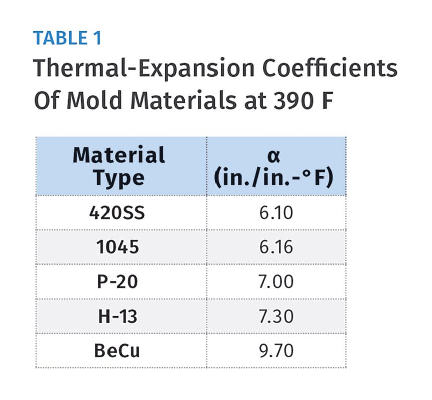
ΔL is the increase in length of the hot sprue at the processing temperature. La is the unsupported length of the hot sprue at ambient temperature; Tp is the processing temperature of the molding material. Ta is the ambient temperature (typically 68 F); α is the coefficient of thermal expansion of the material—typically steel. Ta and La are for the most part, fixed values; α is also a fixed value, but are you using the right one? I checked the coefficients of thermal expansion for various types of steels used in injection molds (see Table 1). They ranged from 6.1 to 7.3 Å~ 10-6 in./in.-.F. The difference between the highest and lowest values is an extremely small number (0.0000012 in./in.-.F), but it’s an important one. If you have a 10-in.-long hot sprue running at 600 F, and your coefficient of thermal expansion is off by just 0.5 Å~ 10-6 in./in.-.F, that’s a difference of 0.003 in.
Depending on the molding material, that can mean the difference between flashing or hobbing the mold. Using a “generic” expansion coefficient for every type of mold steel is a mistake. These coefficients not only vary from one type of steel to another, they also vary from one supplier to another.
If all this isn’t confusing enough, it turns out that the coefficient of thermal expansion for tool steel really isn’t a fixed value. The value increases as the steel temperature increases. How do you account for that?
And what about the mold base itself?
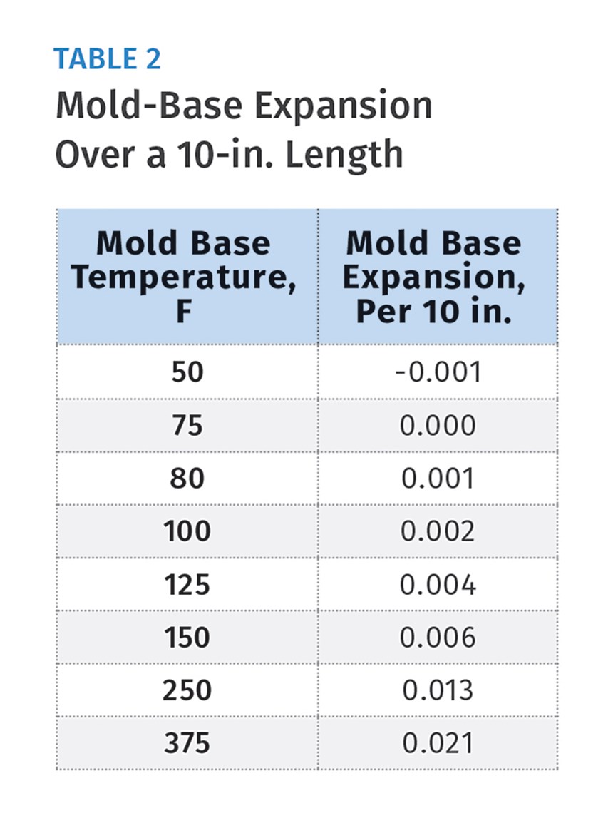
The same formula used to calculate how much the hot sprue will increase in length should also be used for the mold base (Table 2). The amount of thermal expansion is negligible at mold temperatures below 80 F, but higher temperatures are definitely a factor to consider. For example, if you’re running PEEK with a mold temperature of 375 F and the hot sprue is 10 in. long, the mold plates over that distance will grow about 0.021 in. If you don’t take that into consideration, you’re going to mold a disk whether you want one or not.
Molding a thin disk guarantees the hot sprue will never extend beyond the parting line.
Instead of pulling your hair out trying to calculate the perfect amount of linear thermal expansion, the easiest way to deal with the problem is to heat the sprue, and if necessary, the mold base, up to the processing temperatures. Measure the distance between the face of the sprue and the parting line and adjust accordingly. That will get you very close to being “spot on” without all the mathematical hassle.
If you performed the measurement procedure above, the only thing that can cause a problem is if the processing temperatures change out on the production floor. Unfortunately, the processing temperatures out on the floor almost always differ from what was recommended and designed for.
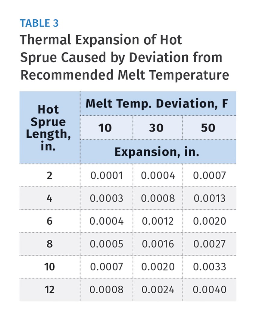
All molding materials have an acceptable melt-temperature range, as specified by the manufacturer. That range can be as much as 50° F or more. It’s not uncommon for a processor to exceed these upper and lower specified temperature limits in order to fill out the cavities or improve the aesthetics or dimensions of a part. It’s called “processing around” a part- or mold-design issue. Table 3 shows that unless you have a fairly long hot sprue and a fairly high temperature deviation, the hot sprue really doesn’t expand as much as you might think.
With some regularity, problems with a thermocouple or a controller can cause the temperature of the hot sprue to increase—sometimes through the roof. These are the most common reasons:
- The thermocouple does not have proper contact with the steel.
- Incorrect wiring of the thermocouple or heater zones in the electrical connector.
- Frayed thermocouple wires contacting each other.
- A K-Type thermocouple was installed, when a J-Type was required. (Note: In the USA, J-type leads are red and white. Other countries do not follow the same color-coding scheme.)
- A control module fails in the “closed” condition.
- A supervisor detects a thermocouple problem and switches the controller into manual mode at too high a power setting.
A less common reason for temperature override is the quality of the controller itself. I once started up six brand-new hot-runner molds with six brand-new controllers. When we turned the controller on for the first mold, all the zones shot right past their setpoints. The same thing happened to the second mold, and the third, and so on for all six molds. It turned out that a blown-film extruder in an adjoining room had a very large DC motor on the same power line. It was spewing out a massive amount of electrical noise, which affected all the controllers. It took an oscilloscope and a very savvy tech-service rep to solve that one.
So far, I’ve given you several good reasons to mold a disk, and very few to have the hot sprue “kiss-off” against the B-plate. Now let’s discuss what happens to the process with and without a disk. Some people say that if you don’t mold a disk, the face of the hot sprue will contact the B-plate, which will suck the heat out and change the intended heat profile. To some extent, that’s true; but, depending on the mold, having the heat sucked out of the face of a hot sprue can either be a good thing or a bad thing.
You may not want to mold a disk if the cycle time is fairly fast, the gate orifice is relatively large, or the material is a type that likes to string, such as ABS. The additional heat transfer helps reduce the damaging strings from forming by increasing the solidification rate. It’s the exact reason some molds are designed with water-cooled bushings around a hot-sprue tip.
Not molding a disk increases the rate of heat being sucked out of the hot-sprue tip and should reduce the risk of stringing. Conversely, you may want to mold a disk if the cycle time is fairly slow, the gate orifice is relatively small, or the material is the type that sets up fast, like crystalline nylon. Not molding a disk could suck out too much heat and can cause a cold slug to form behind the gate. Cold slugs require a tremendous amount of pressure to dislodge at the start of injection. I’m sure you’ve all heard a loud popping sound or felt the injection carriage shake when that happens. To make matters worse, this cold slug needs to get trapped by a cold well or runner overflow before it makes its way to the cavity. Molding a disk will reduce the rate of heat being sucked out of the hot sprue tip. This should reduce the risk of forming a cold slug.
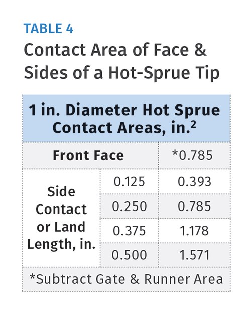
There’s a lot of conjecture about just how much heat is or isn’t transferred from the face of the hot sprue to the moving half of the mold when you don’t mold a disk. If the heat transfer is really that important, and sometimes it really is, then the focus should be more on the outside contact or land area of the hot sprue tip—not the face of the tip. If you don’t mold a disk, the face of the tip is only contacting steel for a portion of the molding cycle while the mold is closed. But the land area of the tip is always in contact with the adjoining steel.
Table 4 shows that the amount of possible contact area on the side of a hot-sprue tip can be considerably less or considerably more than that of the face of the tip. The amount of land length in the mold, as specified by hot-sprue manufacturers, varies tremendously. I like to hedge my bets and often increase the land length as much as possible.
In fact, for sprues with large orifices, I prefer a shorter nozzle body with an extended nozzle tip, specifically to increase the land length. It’s a steel-safe condition that can easily be reduced if there’s an issue. I once helped tweak the process of a high-volume mold running a very fast cycle. Every second meant tens of thousands of dollars per year. We tested tips out of H-13 steel, 420 stainless, and BeCu alloy.
We also varied the amount of outside contact of each of those tips. The goal was to get the fastest gatefreeze time to minimize the cycle, but not too fast, which would create cold slugs or cause the mold to be difficult to start up. If the gate-freeze time was too long, it would extend the cycle, or cause stringing. The diameter of the gate orifice was a fixed dimension—just large enough to keep the injection pressures at a reasonable value for the given wall thickness and flow length.
The orifice diameter and molding material were the predominant factors in determining which type of metal to use for the hot-sprue tip, and how much land length was needed to obtain the ideal solidification rate to achieve the fastest possible cycle.
Because of this investigation into whether to mold a thin disk, I have reversed my old-school opinion. In all but the most extreme cases, the amount of heat loss from a hot-sprue tip to the moving half of the mold is probably not much of a controlling factor. Therefore, I now suggest intentionally molding a disk with a thickness of roughly 25% of the wall thickness of the part. But don’t forget to maximize the land or bearing length of the hot-sprue tip and pay particular attention to the cooling channels near or around the tip. This way, you prevent damage to the parting line of the mold caused by a variety of potential issues, and you maintain the ability to adjust the gate solidification rate by varying the tip’s land length and cooling temperature to prevent cold slugs or strings.
Lastly, kudos to those of you who realize that much of what I said here about hot sprues feeding a cold runner in a two-plate mold also applies to a hot sprue in a three-plate mold, and to molds with various other types of hot-feed systems.
ABOUT THE AUTHOR: Jim Fattori is a third-generation injection molder with more than 40 years of molding experience. He is the founder of Injection Mold Consulting LLC, and is also a project engineer for a large, multi-plant molder in New Jersey. Contact jim@injectionmoldconsulting.com; injectionmoldconsulting.com.
Related Content
Why Shoulder Bolts Are Too Important to Ignore (Part 2)
Follow these tips and tricks for a better design.
Read MoreHow to Select the Right Tool Steel for Mold Cavities
With cavity steel or alloy selection there are many variables that can dictate the best option.
Read MoreWhy Shoulder Bolts Are Too Important to Ignore (Part 1)
These humble but essential fasteners used in injection molds are known by various names and used for a number of purposes.
Read MoreThree Key Decisions for an Optimal Ejection System
When determining the best ejection option for a tool, molders must consider the ejector’s surface area, location and style.
Read MoreRead Next
How Sprue Pullers Help Prevent Molding Issues: Part 2
A vital secondary function of sprue pullers is to act as a cold well to trap solidified material left in the machine-nozzle tip.
Read MoreMaking the Circular Economy a Reality
Driven by brand owner demands and new worldwide legislation, the entire supply chain is working toward the shift to circularity, with some evidence the circular economy has already begun.
Read MoreLead the Conversation, Change the Conversation
Coverage of single-use plastics can be both misleading and demoralizing. Here are 10 tips for changing the perception of the plastics industry at your company and in your community.
Read More


