Troubleshooting Vent Flow Problems in Single-Screw Extruders
Vent flow can be a costly problem and a housekeeping nuisance. Here is some advice on how to eliminate it.
Two-stage extruders with a vent port downstream from the first stage are common in many types of plasticating extrusion processes where volatiles or entrained air need to be removed. These extruders are used for the processing of styrenics, polycarbonate, pelletization of post-consumer recycle (PCR), and repelletization of foam in-plant recycle, to name a few.
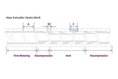
To be economically viable, the extruder must be stable, operate at high rates, and remove volatile materials from the resin. If the volatiles are not removed for sheet extrusion, for example, surface pitting and visible defects can be seen on the product. A schematic of a two-stage extruder is shown in Fig. 1.
The pellets fed to the hopper are conveyed forward, melted, and then pumped out of the first stage of the screw and into the deep vent channels in the second stage. The first stage of the extruder operates like any extruder with just a single stage. The metering section of the first stage controls the rate and specific rate of the extruder. If operating properly, the first-stage metering channel is full of resin and under pressure. When the molten resin enters the vent channels in the second stage, the deep channels are only partially filled and at zero pressure. At zero pressure, volatile components can be removed through the vent opening.

FIG 1 Schematic of a two-stage extruder. (Images: M. A.Spalding)
Downstream from the vent opening, the channels become shallower in the second stage, and they become full and start to build pressure. Over the length of the second-stage metering section, the pressure increases to the level needed to operate the downstream equipment. The second stage cannot control the rate. If the second stage controls the rate, then pressure will occur upstream and underneath the vent opening, causing resin to flow out of the vent. The term “vent flow” is commonly used to describe that effect.
The ability of the second stage to pump and pressurize the resin depends on the metering-channel depths and the length of the second-stage metering channel. For screws with constant lead lengths, the pump ratio for the second stage is simply the channel depth of the second-stage meter divided by the channel depth of the first-stage meter. That ratio depends on many factors, including viscosity and discharge pressure, but it usually ranges from about 1.3 to 2. That is, the pumping ability of the second stage due to just rotation is 1.3 to 2 times higher than that for the first stage. This design allows the first-stage metering channel to control the rate of the extruder. Screw designers specify the dimensions of the first and second stage to obtain the target discharge temperature and pressure while not causing pressure in the vent channels that would lead to vent flow.
A common problem with two-stage extruders is the flow of molten polymer out of the vent opening and onto the floor. Years ago I was called in to study a two-stage extruder running a styrenic resin. The extruder was discharging to the downstream equipment at a rate of 950 lb/hr and about 150 lb/hr was coming out of the vent port. The material that went onto the floor was scrapped, causing higher costs to the business and a housekeeping nuisance. Moreover, the extruded product was inferior due to surface defects since volatile components were unable to escape via the vent.
A common problem with two-stage extruders is the flow of molten polymer out of the vent opening and onto the floor.
There are only two root causes for vent flow. The first root cause is because the screw design does not pump and pressurize the resin sufficiently, causing pressure to occur in the vent channels. For normal operations, the deep channels underneath the vent opening are partially filled with resin and at zero pressure. If the second stage is not designed correctly, the vent channel can be operating full of resin and under pressure. The pressure will cause the resin to flow out of the vent opening. Simple calculations can be used to determine whether the second stage can generate the pressure to run the die while not causing vent flow. These calculations are beyond the scope of this article. Screw designers and resin suppliers, however, understand these calculations and they are eager to assist.
The second root cause is a poorly designed or missing vent-flow diverter. The diverter is a small device that is inserted into the vent opening, as shown in Fig. 2. As the screw rotates, the molten resin is pushed forward by the pushing side of the flight. The trailing side of the flight is void and the channel is at zero pressure. The elasticity of the material can cause the resin to be pushed out of the barrel cylinder and into the vent area. The recessed area of the diverter pushes the resin back into the barrel.
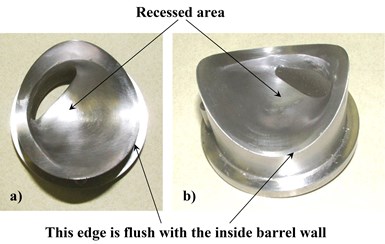
FIG 2 Examples of typical vent flow diverters.
If the diverter is not installed, then this material that is pushed into the vent opening is not pushed back into the barrel. Each rotation of the screw will push more resin into the vent. The styrenic resin extruder previously discussed had a high level of vent flow because of a damaged vent-flow diverter. When a new diverter was designed and built, the vent flow stopped.
If an extruder is experiencing vent flow, the first check should be to see if a diverter is installed in the vent.
Vent-flow diverters can be damaged by mishandling or they can be installed backwards where the vent opening is on the opposite side of the channel. Machine designers will typically design the vent diverter such that it can only be installed one way, eliminating the possibility of installing backwards. It is more common for the vent diverter to be missing.
If an extruder is experiencing vent flow, the first check should be to see if a diverter is installed in the vent. If there is a diverter in place, the position of the vent opening should be studied to make sure that it is positioned according to Fig. 3. If the diverter looks like it is installed correctly, then the next step is to calculate the maximum pressure that the second stage can deliver before vent flow occurs. As previously discussed, this calculation is beyond the scope of this article, but screw designers and resin suppliers can help. New vent diverters can be obtained from the extruder manufacturer or from screw suppliers.
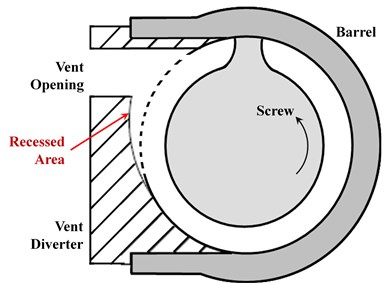
FIG 3 Schematic of vent flow diverter.
All extruders can be forced into vent flow by increasing the discharge pressure. The discharge pressure can be increased by using finer screens in the screen pack or by increasing the inlet pressure to a downstream gear pump. As a diagnostic test, an extruder that is vent flowing may stop vent flowing if the discharge pressure can be reduced. Reducing the discharge pressure can be done by removing the screens and running the gear pump at the minimum acceptable inlet pressure. If the vent flow stops it indicates that the screw design is not correct for the process, causing pressure to occur underneath the vent opening. If vent flow still occurs, the diagnosis is inconclusive since it could be the vent diverter is not correct or high pressure still exists in the vent area.
Vent flow can be a costly problem and a housekeeping nuisance. In all cases, vent flow does not need to be tolerated. It can be eliminated by either a properly designed vent-flow diverter or via screw design.
ABOUT THE AUTHOR: Mark A. Spalding is a Fellow in Packaging & Specialty Plastics and Hydrocarbons R&D at Dow, Inc. in Midland, Mich. During his 37 years at Dow, he has focused on development, design, and troubleshooting of polymer processes, especially in single-screw extrusion. He co-authored Analyzing and Troubleshooting Single-Screw Extruders with Gregory Campbell. Contact: 989-636-9849; maspalding@dow.com; dow.com.
Related Content
How Polymer Melts in Single-Screw Extruders
Understanding how polymer melts in a single-screw extruder could help you optimize your screw design to eliminate defect-causing solid polymer fragments.
Read MoreReduce Downtime and Scrap in the Blown Film Industry
The blown film sector now benefits from a tailored solution developed by Chem-Trend to preserve integrity of the bubble.
Read MoreSingle vs. Twin-Screw Extruders: Why Mixing is Different
There have been many attempts to provide twin-screw-like mixing in singles, but except at very limited outputs none have been adequate. The odds of future success are long due to the inherent differences in the equipment types.
Read MoreMedical Tubing: Use Simulation to Troubleshoot, Optimize Processing & Dies
Extrusion simulations can be useful in anticipating issues and running “what-if” scenarios to size extruders and design dies for extrusion projects. It should be used at early stages of any project to avoid trial and error and remaking tooling.
Read MoreRead Next
The Right Way to Design Vents in Single-Screw Extruders
Designing vents for single-screw extruders requires understanding of polymer flow in the screw channels. Some designs are more effective than others. Here are some guidelines.
Read MoreMaking the Circular Economy a Reality
Driven by brand owner demands and new worldwide legislation, the entire supply chain is working toward the shift to circularity, with some evidence the circular economy has already begun.
Read MoreFor PLASTICS' CEO Seaholm, NPE to Shine Light on Sustainability Successes
With advocacy, communication and sustainability as three main pillars, Seaholm leads a trade association to NPE that ‘is more active today than we have ever been.’
Read More
