Unraveling the Complexity of Single-Screw Scale-Up
Variables such as shear rates, melting rate, residence time and conductive heating are all influenced in the scale-up.
Scale-up of single screws can be a surprisingly complex issue when you consider all the variables and their interactions. One of the first scale-up rules was defined by Carley and McKelvey in a 1953 article published in the journal, Industrial and Engineering Chemistry. They showed that output and power consumption varied with the ratio of the square of the screw diameters (D1/D2)2 when at the same screw rpm and channel depth for screws having the same geometry (channel width and flight width). However, shear rate is determined by the peripheral screw speed rather than the rpm. When compared at the same peripheral speed and the same channel depth, the outputs scale up as the simple ratio of the screw diameters.
The squaring effect of the output comes from the change in channel volume. In the accompanying illustration, a 2-in. and a 4-in. screw have the same channel depth. As the screw size increases, the channel volume increases by the square of the ratio of the diameters. In this case, the volume of one turn of the 4-in. screw was calculated to be exactly four times the volume of one turn of the 2-in. screw.
As a result, the diameter scale-up (D1/D2)2 holds true for the same channel depth and screw rpm.
In a 2006 issue of Polymer Engineering and Science, an article by Chris Rauwendaal provided a very thorough analysis for all aspects of scale-up, including shear rate, melt conveying rate, residence time, shear, conductive and dissipative melting capacity, solids conveying rate, power consumption, heat transfer, mixing, and specific energy consumption, for a total of 14 different scale-up factors. It’s a very comprehensive and accurate analysis but requires an expert to resolve the best balance between scale-up factors.
In 1974 I was fortunate to be given a two-week individual training course by Bruce Maddock at Union Carbide’s Bound Brook, N.J., development lab. It was common practice at that time to scale up the channel depth using the inverse or the square root of the diameters: (D1/D2)0.5. Maddock was at that time finalizing a technical paper in which he taught that scale-up of channel depths was more closely represented by the ratio of the diameters to the 0.7 power. That ratio, (D1/D2)0.7, was representative of maintaining similar melt temperatures and melt quality across two extruder sizes that were geometrically similar in flight lead, flight width and so forth.
At that time, Carbide had one of the largest development programs in the industry—with extruders up to 4.5 in. for testing—so that there was quite a bit of actual data to support the calculation. Additionally, the data was collected making blown film, so melt quality was very clearly demonstrated. I have used that same approach for sizing the metering depth for hundreds of screws with the same lead angle and proportional configuration. I have added a small correction for polymers with strong shear-thinning behavior, which becomes important when the screws are to be run a vastly different peripheral screw speeds.
The shear rate, melting rate, residence time and conductive heating are all influenced in the scale-up. Shear rate in the screw channel is described as (π D N/h) where:
D is the diameter to the first power;
N is the revolutions/sec;
h is the channel depth.
It’s clear then that the use of the same channel depth with an increase in screw size will produce a much different shear rate and result in differing melt quality and melt temperature. It’s also clear that there is more consistency between the square of the diameter ratio to 0.7 power than the 0.5 power, compared with the first power of the diameter used in calculating the shear rate.
Maddock and others determined that the 0.7 power of the ratio of the screw diameters was a better factor for determining channel depth then the square root of the ratio of the screw diameters, as it takes more fully into account the heat-transfer distances, increased shear heating over the flights due to higher peripheral speed, flight-length ratio, and increased leakage flow over the flights due to the larger flight clearances as the diameter is scaled up. Additionally, heat removal through barrel cooling is reduced because of the ratio of barrel area to output. The use of (D1/D2)0.7 generates a greater channel depth in the scale-up and reduced shear rate to counter those effects.
In conclusion, the use of (D1/D2)0.7 as a scale-up factor for the metering depth of screws with similar geometry and L/D has been found to be a very satisfactory general approach. C.I. Chung, in his 2000 book, Extrusion of Polymers arrived at the same scale-up factor as a “balanced” basis for overall scale-up.
ABOUT THE AUTHOR: Jim Frankland is a mechanical engineer who has been involved in all types of extrusion processing for more than 40 years. He is now president of Frankland Plastics Consulting, LLC. Contact jim.frankland@comcast.net or (724) 651-9196.
Related Content
Understanding Melting in Single-Screw Extruders
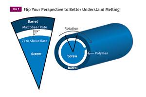
You can better visualize the melting process by “flipping” the observation point so the barrel appears to be turning clockwise around a stationary screw.
Read MoreA Systematic Approach to Process Development
The path to a no-baby-sitting injection molding process is paved with data and can be found by following certain steps.
Read MoreWhy Shoulder Bolts Are Too Important to Ignore (Part 1)
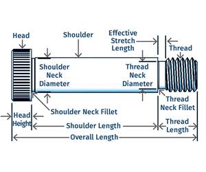
These humble but essential fasteners used in injection molds are known by various names and used for a number of purposes.
Read MoreFundamentals of Polyethylene – Part 6: PE Performance
Don’t assume you know everything there is to know about PE because it’s been around so long. Here is yet another example of how the performance of PE is influenced by molecular weight and density.
Read MoreRead Next
For PLASTICS' CEO Seaholm, NPE to Shine Light on Sustainability Successes
With advocacy, communication and sustainability as three main pillars, Seaholm leads a trade association to NPE that ‘is more active today than we have ever been.’
Read MoreMaking the Circular Economy a Reality
Driven by brand owner demands and new worldwide legislation, the entire supply chain is working toward the shift to circularity, with some evidence the circular economy has already begun.
Read MoreSee Recyclers Close the Loop on Trade Show Production Scrap at NPE2024
A collaboration between show organizer PLASTICS, recycler CPR and size reduction experts WEIMA and Conair recovered and recycled all production scrap at NPE2024.
Read More
.jpg;width=70;height=70;mode=crop)


