Use Molding Simulation To Avoid Surface-Finish Defects
It’s not just for successful mold filling and cooling. Simulation can help predict and overcome cosmetic defects in molded parts.
Sink marks. Weld lines. Splay. Blush. Scuff marks. Everyone involved with developing molded components should know this list very well (and it’s a really long list). The unavoidable truth is that cosmetic factors significantly affect the perceived quality of a plastic part, whether they influence its functionality or not. Many molded parts only serve an aesthetic purpose, making cosmetic defects an even bigger issue. In both cases, the fundamental challenge is that the prevalence and severity of cosmetic defects are difficult to assess using intuition and experience alone.
That’s where computer-aided simulation technology comes in. Injection molders are generally familiar with use of such software to predict and optimize mold filling and cooling. But its role in anticipating, troubleshooting, and resolving or—better yet—preventing surface defects is less familiar. In this article, we will show how a combination of good design practices and simulation technology, like Autodesk Moldflow, can help engineers deal with cosmetic defects more effectively.
CLARIFYING THE CHALLENGES
One of the reasons why surface finish is so problematic is simply the number of decisions involved. The matrix of choices with respect to part geometry, materials, processes, mold design, and mold textures—and how the consequences of each choice affect other decisions—makes cosmetic defects difficult to visualize until you see the molded part.
Depending on your role, you may not always have control over these decisions. For example, you may find that the most straightforward way to solve a cosmetic issue would be using a different material color, mold texture, or process type, but that choice may not be available given brand constraints, the project’s budget, or the schedule.
A third challenge is the nature of cosmetic defects. They are primarily visual phenomena that are hard to quantify and difficult to simulate. Surface textures and colors are not easy to characterize with data in the same way as mold-filling conditions (such as flow-front temperature, shear, or velocity). Defects may be minimized or exaggerated depending on the lighting intensity, direction, source spectrum, viewing time, angle, and distance.
For example, an off-white color will mask defects better than gray or (even worse) black. Specific surface finishes can amplify or reduce the visibility of surface defects. The nature of a defect, such as sink-mark depth or width, may also increase the odds of visual detection. The color of objects around the part influence this effect as well. As a result, even the most sophisticated simulations may not be able to fully represent the end user’s visual experience.
The good news is that we’re making progress. Some recent trends are pushing the envelope of visualization:
- Exporting warped geometry as a CAD file (.sat or .step) for easier comparison with the original model;
- Exporting sink-depth predictions from simulation tools to visualization tools (VRED or 3Ds Max);
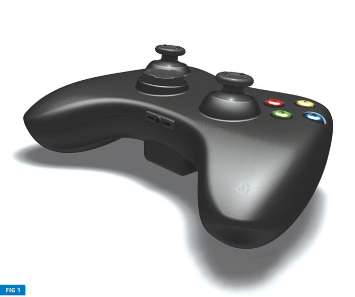
- High-quality rendering to more closely match reality in terms of color, texture, and lighting (see Fig. 1). Meanwhile, manufacturers are moving ahead with new techniques to combat cosmetic defects, including more sophisticated thermal control of the mold, 3D texturing technologies, liquid silicone rubber (LSR) injection molding, and component integration—such as multi-shot techniques.
Nevertheless, engineers will always need reliable ways to identify and manage the risk of cosmetic issues. This, again, is where simulation comes in.
FOUR KEY VARIABLES
To overcome the challenges posed by cosmetic defects, engineers have four primary variables to explore. Depending on the scenario, simulation can help engineers consider ways to mitigate risks in the design phase or accelerate the troubleshooting process if defects show up in a prototype.
1. Process type: Anytime you have the ability to explore processes, it will change your approach to evaluating aesthetics. For Example, gating thick to thin is a trusted, conventional approach. But gating into a large, thick area can cause jetting, depending on the type of gate (direct drop, tunnel, tab, or lap style). Manufacturing the same part with gas assist, coining or two-shot technologies could eliminate this source of surface blemishes.
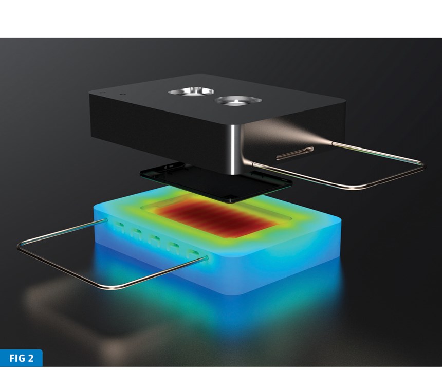
Another way to do this is to replace the pack-and-hold phase with microcellular foam growth, in which case it is ideal to gate into thin areas to control and contain bubble excitation. Of course, engineers could also vary the mold temperature to create a very resin-rich surface that improves finish quality. An example of this would be the use of rapid heating and cooling or induction heating (Fig. 2). Many of these process choices can be simulated, creating opportunities to see which one is most appropriate for ensuring the desired level of surface finish quality.
2. Material choice: Not all materials are created equally with respect to cosmetics. Simulation allows you to explore how material choices affect process- ability and surface defects. Understanding the properties of different materials can provide a plastic engineer with clues about how to design gates to avoid a defect like gate blush, for instance. Fillers, such as fibers or metal flakes, can also have a significant impact on the product’s appearance, and simulation can be used to get a handle on this.
Another area where simulation can be advantageous is in the study of weld lines. It is common for plastics engineers to examine the angle of the melt front as well as the temperature and
pressure to identify regions where melt fronts are separated by an obstacle (the part’s geometry or multi-gates) and then recombine. These dynamics affect both the strength of the part and its cosmetics. With simulation, you can try the options available to you and let the software iterate to help you choose the best material, gate location(s), and geometry sooner.
3. Part geometry: Simulation excels at the classic DFM (design for manufacturing) approach, giving engineers a reliable way to examine the impact of thickness variation, such as rib-to- surface ratios, thick-to-thin ratios, and flow phenomena. A quick check of drafts and undercuts can also be useful when evaluating mold cost, manufacturability, texture depths, and the potential for ejection distortion (such as scuff marks).
Flow quality and thickness go hand in hand. The cardinal rule for balanced fill is uniformity—whether of melt pressure, temperature, velocity, or volume/ thickness—which is important for cosmetics too. Flow hesitation effects are often visible and are very thickness dependent. Injection molding simulation can quickly help identify problems using contour plots to identify flow-related defects, as well as using flow-front velocity, shear stress at the wall, temperature at the flow front, and other parameters calculated by the software. Simulation software can also ensure that a mold fills easily and uniformly without significant temperature variations, and also help you predict jetting effects, weld-line positions, and air traps.
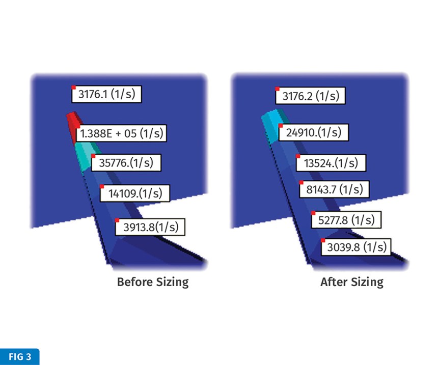
4. Mold design: Mold design is an extensive area to explore, in particular gate design and blush. Gate area and thickness transitions matter a great deal for cosmetics, and shear rate is a key result to focus on. Simulation offers a proven way to see whether, for example, changing a circular gate to a more rectangular shape can reduce shear rates. Simulation also makes it easy to find the best gate locations and flow rate, then size the gates to minimize the shear rate (Fig. 3).
In addition, simulation can help engineers look at new ways to avoid surface defects, such as rapid heating and cooling (aka “variotherm” molding). Simulations can show a transient or dynamic thermal analysis of the mold and the interface of the plastic and tool steel. Induction heating is another approach that can be modeled to optimize temperature distribution without affecting cycle time.
Another choice engineers have to make is the type of runner system and gate (cold gate, hot tip, or valve gate). Simulation can capture the mechanics of opening and closing, such as the valve-pin opening speed, as well as create a detailed flow- front profile. This profile identifies potential hesitations that may change flow-front speed and the material melt properties, which have a significant effect on the imprint of the texture and surface finish.
A CASE STUDY
A quick case study of an actual part can illustrate how all of this complexity comes together to affect the part’s cosmetic quality—and how simulation can help find a solution.
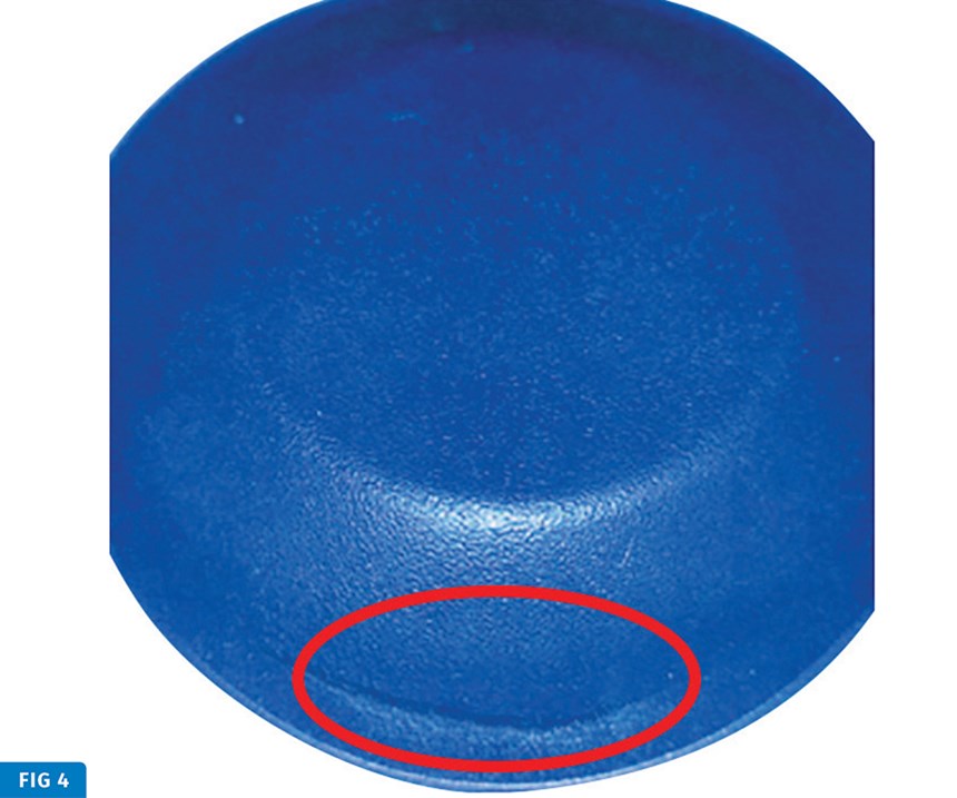
In this case, the part was a TP elastomer molded with a two-shot process. It was cosmetically challenging due to the
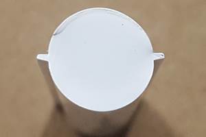
dispersion of the colorant. However, initial runs were perfect. Then the program changed both the material and the colorant, creating a defect in the bottom of the part (Fig. 4).
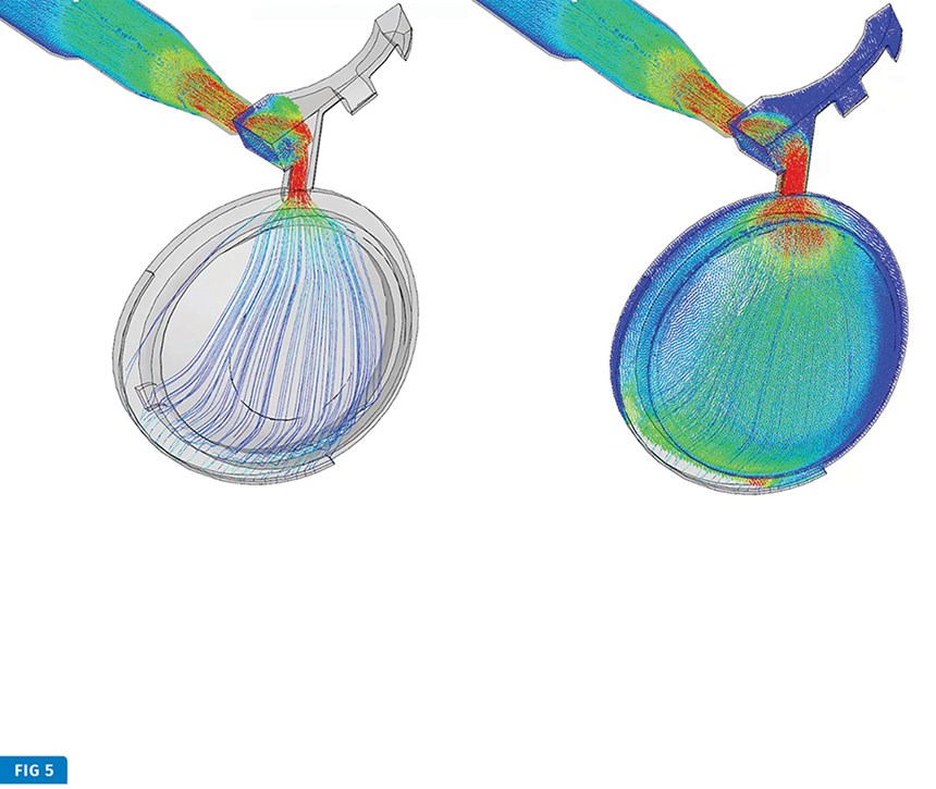
Overlaying various analyses—including pathlines, flow-front progression, and single contour—within the simulation software helped engineers visualize the flow velocity and identify the hesitation near the rim that was causing the flow-front speed to vary and resulted in a visual defect (Fig. 5).
This example highlights how the decisions we make as engineers can have unpredictable effects on surface quality. In this case, the hesitation was present in both situations. But one material masked it, while the other material exaggerated it.
The part volume in this case was very small, which made it hard to control the molding process. Some process changes did alleviate the defect to a degree, but the underlying cause of the hesitation was part geometry—specifically a thickness variation that resulted in the hesitation and the ensuing racetrack effect. Once the root cause of an issue was identified, it quickly became apparent what to do next.
All plastics engineers face similar challenges when it comes to optimizing surface-finish quality, but there is a huge array of options available to resolve problems before they become too expensive to fix. However, the resulting tradeoffs are not always easy to quantify. Judging what is acceptable is often subjective and application-dependent.
The underlying causes of surface-finish defects, however, are not subjective. Simulation provides a wide range of analytic tools engineers can use to examine them and understand how choices in process, material, geometry, and mold design might change the look of the final product.
Simulation technology, such as Autodesk Moldflow, can provide insight quickly, enabling engineers to consider more options within a tight schedule and reach a satisfactory answer sooner.
ABOUT THE AUTHOR: Brian Pelley, Moldflow Technical Specialist with AutoDesk, Inc., is a plastics engineer with more than 20 years’ experience in simulation, CFD, and FEA with large OEMs and custom manufacturers. His areas of expertise include analysis, support, training, consulting, and sales. Contact: brian.pelley@autodesk.com; autodesk.com.
Related Content
The Effects of Time on Polymers
Last month we briefly discussed the influence of temperature on the mechanical properties of polymers and reviewed some of the structural considerations that govern these effects.
Read MoreWhere and How to Vent Injection Molds: Part 3
Questioning several “rules of thumb” about venting injection molds.
Read MoreInjection Molding: Focus on these Seven Areas to Set a Preventive Maintenance Schedule
Performing fundamental maintenance inspections frequently assures press longevity and process stability. Here’s a checklist to help you stay on top of seven key systems.
Read MoreFundamentals of Polyethylene – Part 6: PE Performance
Don’t assume you know everything there is to know about PE because it’s been around so long. Here is yet another example of how the performance of PE is influenced by molecular weight and density.
Read MoreRead Next
Mold Simulation: Get Best Results With Good Materials Data
Want the best results from your flow analysis software? Of course you do. But you stand a better chance for success if you pay particular attention to the material data used by the software.
Read MoreFor PLASTICS' CEO Seaholm, NPE to Shine Light on Sustainability Successes
With advocacy, communication and sustainability as three main pillars, Seaholm leads a trade association to NPE that ‘is more active today than we have ever been.’
Read More
