Insert overmolding is an exacting technique in injection molding, but in its early days, it was not often handled by a robot—it usually required the assistance of human hands, especially for inserts with more difficult geometry. The robot technology and know-how of those days was not yet very capable for insert handling. Loading inserts into the tool was done—and sometimes still is—manually by workcell operators, especially for inserts that presented challenges in size, shape or the need for precise location and orientation.
For years, horizontal machine operators would wait for the mold to fully open, let the parts fall, slide open the safety gate, carefully orient and hand-load the inserts into the mold, close the gate, and continue the overmolding cycle. It was an inefficient and labor-intensive method; the opening and closing of gates lengthened cycle times; and it was often prone to inaccurate insert orientation. Vertical molding machines had similar challenges, but this article focuses on horizontal-clamp machines, which are much more common among molding shops and are favored for higher production insert molding. And because top-entry robot design favors horizontal machines, vertical presses did not experience the benefit of technological advances in this type of automation.
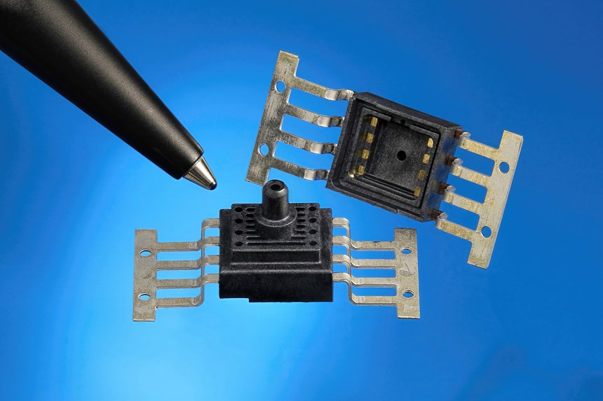
Micro-Insert Part Examples
Time is technology’s friend, and robot technology has much improved, particularly for horizontal injection molding and top-entry linear robots. Nowadays, most molders with higher production runs for overmolded insert parts have automated the process with top-entry linear robots to streamline the process, save direct-labor cost, and improve quality control.
But what works for common overmolding applications with “normal” sized inserts and parts, is not necessarily sufficient for the micro-sized inserts and parts that are increasingly common in this era of miniaturization in electronics, medical devices and micro-mechanical systems. A dozen of these inserts might fit on a penny. This scale offers a much greater challenge to molders and robot suppliers alike.
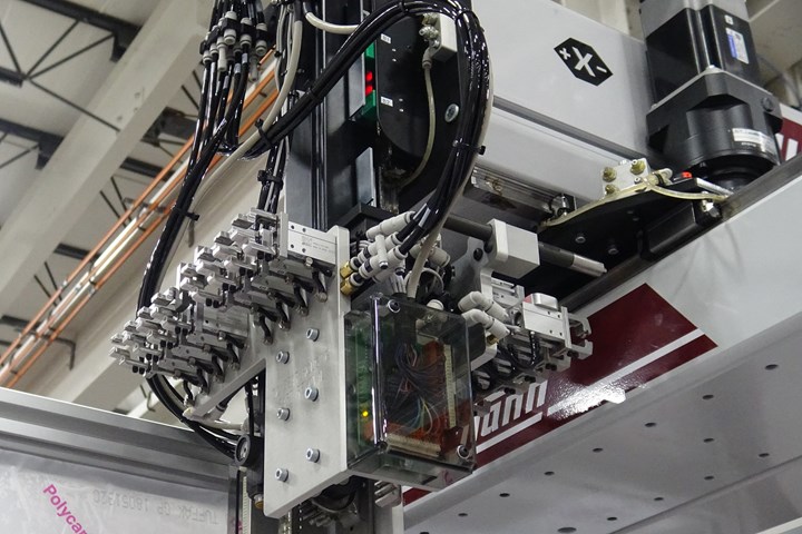
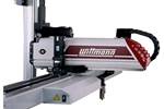
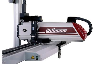
Wittmann W822 robot with micro-insert EOAT. Most insert molders with higher production runs are using horizontal injection presses with top-entry robots.
Micro Size, Big Challenges
At the micro scale—say, less than 3 mm—insert overmolding is still often done manually (or not at all) because of the challenges of automated handling such tiny inserts. This means the part design often defaults to a two-piece assembly rather than an integrated one-piece overmolding. Why? Because molders and part designers aren’t always aware of the capability of the latest generation of injection molding robots or the capability of the suppliers’ custom automation engineering groups to manage and successfully implement such workcells.
Micro applications may not be suited to your existing older-generation robot that still “goes through the motions.” But today’s top-entry linear robots feature such advances as higher precision (<1 mm) drive trains, multi-axis precision servo motors, and software control. When seen from a distance on a shop floor, today’s higher-tech top-entry linear robots don’t appear much different from earlier models of 20 years ago. But they are, in fact, more accurate, more programmable, more capable, and easily integrated with custom automation. Just as important, some robot suppliers’ custom automation engineering capabilities have grown to match the more advanced-generation robots they supply.
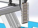
EOAT presenting parts to a single Cognex camera at lower right.
In addition, “in-workcell” devices, sensors and quality-control technology have also improved for precise insert applications. An example is the use of more advanced, yet cost-effective modern vision sensors, proximity sensors and other technologies to ensure that inserts are present, in the correct location and orientation, with very high precision. Combine this with advances in the use of insert feeders, escapements, end-of-arm tooling (EOAT) technology, and workcells have evolved to become very efficient and cost-effective for overmolding even the most challenging of micro-inserts.
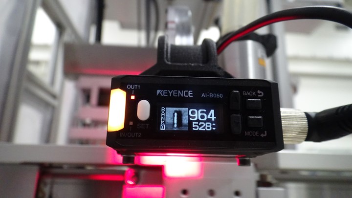
Insert orientation check by camera.
And critically, in terms of project management, the molder can have confidence in a qualified primary robot supplier to take responsibility for the complete robot and automation workcell, so the molder does not have to go to a separate third-party integrator for special insert-molding applications. Managing a project with one supplier has to be better than managing two, right?
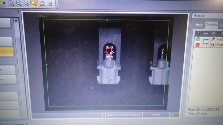
Camera inspection shows insert missing (red box).
Real-World Examples
High-precision micro-insert molding is now being successfully implemented on precision horizontal injection molding machines in the 15-ton to 165-ton range with molds “smartly” designed to facilitate automation from the outset for such applications before mold steel is cut. Here are two illustrative examples of micro-insert applications and the accompanying challenges:
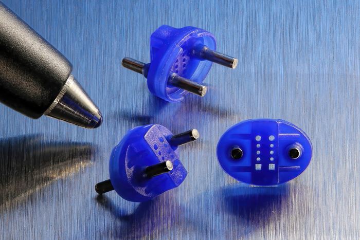
Example Project A is a polyetherimide (Ultem) electrical part less than 1 in. long, with a cylindrical, ceramic polymer insert measuring 1.25 mm (0.0492 in.) diam. The mold has eight cavities, and the locational tolerance of insert placement in each cavity is 0.01 mm (0.0005 in.) The inserts must be oriented front to back.
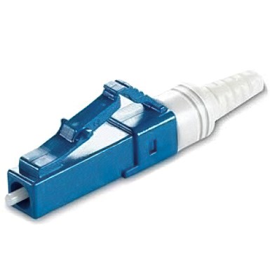
Electrical part in Example A, less than 1 in. long, insert overmolded in eight cavities with Ultem PEI.
The cell includes a 110-ton press, a top-entry linear robot, and vision inspection to confirm that the insert is present and orientation of the substrate in the overmolded part. The robot places the parts on an exit conveyor that indexes by shot.
The challenges for this project included:
• Ensuring the quality of the inserts—i.e., that they are consistently within tolerance and are very free of contamination such as dust, dirt, specs, static or moisture.
• Ensuring that the insert is kept at the correct orientation as it moves from the automated bulk feeding station prior to the overmold process, prior to mold insertion and are correctly seated in the mold cavity before the mold closes. Robot-integrated cameras and vision sensors handled this requirement.
• Careful calculations of mold-steel thermal expansion, which could affect the tolerance of the cavities and seating of the micro-inserts and thus quality of the overmolded part. This is especially critical when processing at such tiny scales and high tolerances.
• Common insert application issues, such as the mold location on the platen had to be perfectly level, square and plumb. This is also required for the mating robot EOAT, even if the latter has mold-engagement alignment pins.
• Machining the EOAT to very high tolerances (±0.0005 in.) from high-quality stainless steel—instead of standard acetal, mild steel or rubber—for the “fingers” gripping the overmolded part. Also required were precision vacuum cavities in the EOAT for insert gripping. Other parts of the EOAT and feeding station are special anodized or hardened materials for wear-and-tear surfaces.
Example Project: B is another electrical part, this one of PBT with a cylindrical metal insert. The insert size is less than 2 mm and it must be inserted into 4 cavities with front-to-back orientation and location tolerance of 0.03 mm (0.0012 in.). Vision sensors check insert orientation and presence in the mold. Cycle time is 15 sec in a 110-ton press.
The challenges for this metal micro-insert overmolding project were very similar to those of Project A. One difference is that metal rather than ceramic inserts must be free of oxidation and coatings to avoid introducing contaminants. On the other hand, ceramic inserts may be more abrasive, and thus special consideration must be made for use of hardened contact surfaces. Also, metal inserts tend to be less fragile and heavier than ceramic inserts, so gripping and handling metal inserts might be a tad easier, though there is nothing easy about handling objects the size of a grain of rice.
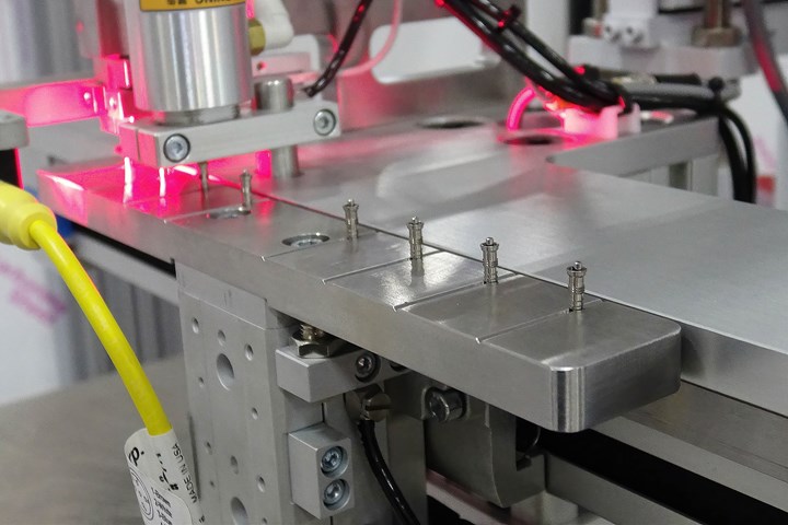
Micro-inserts loaded on pins on a shuttle prior to pickup by a robot. Red light is flash illumination for camera inspection.
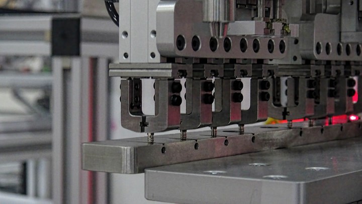
EOAT picking micro-inserts from nest.
Lots of Factors to Control
Other common technical considerations for automated handling of micro-inserts and parts include:
Static charge: Even the tiniest static charges can affect the insert and part, and so tests must be made to determine if the parts or inserts have to be de-static washed or bathed in clean de-ionized air.
Environmental control: Parts and inserts of this tiny scale are more consistently handled if managed in environments with controlled temperature, humidity and air flow. Ambient temperature changes might change the size of the insert, which is critical at precise tolerances. Humidity might negatively affect any hygroscopic polymers; and air flow (such as draft from a nearby vent or doorway) might push the tiny insert or part out of position. Well-designed enclosures and HEPA filters are often used to alleviate these risks, as well as controlling particulate contaminants.
Micro-insert consistency and quality control: Inserts must be very consistent and highly QC’d for dimensions, flash, debris, and other specs by the supplier for consistent inserting and handling.
Micro-parts detection: The need for workcell vision cameras vs. simple vision sensors will be determined through testing. In all likelihood, more advanced vision technology will be needed for tasks such as orientation, inspection, mold-seating confirmation, and post-mold QC. The naked eye is usually not up to such small-scale inspections.
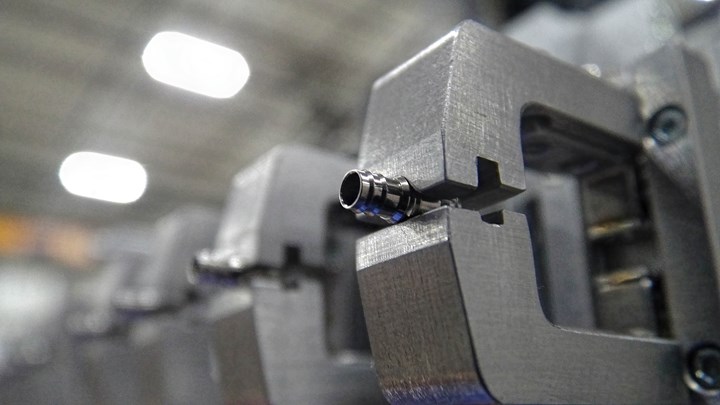
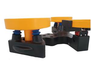
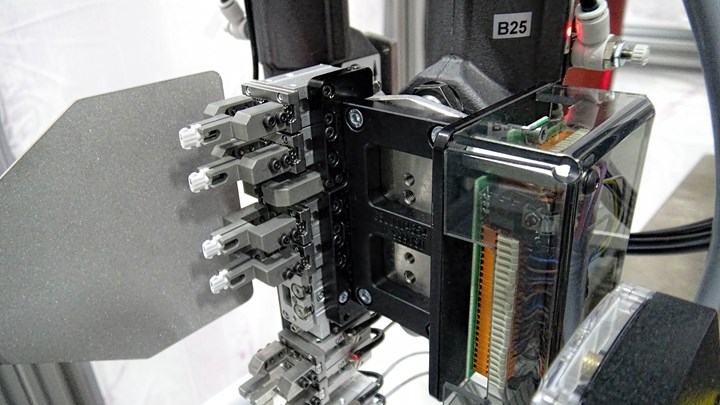
Micro-grippers (shown holding inserts) are machined to very high tolerances and are often made of special materials based on application needs.
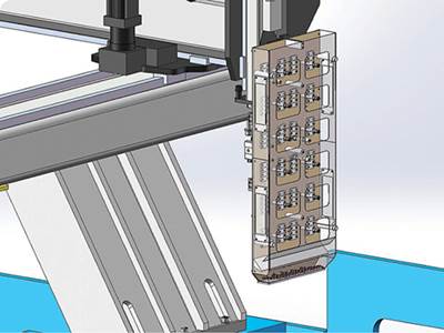
Micro-EOAT gripper precision: The robot and automation grippers and fingers will be machined to very high tolerances and often made of special materials based on the application need.
Insert feeding: This will not be your plain-vanilla, garden-variety bowl feeder; careful consideration will be made to the feeder design and materials of construction, tight tolerances, and creative orientation management with precision sensors confirming each step of the process.
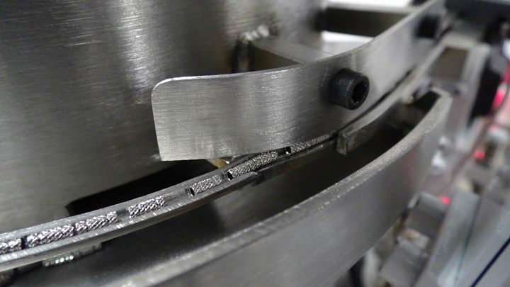
Micro-insert feeding will require more than a “garden-variety” bowl feeder.
Mold seating and engagement: To assist in making the initial setup easy, the robot EOAT often will include a docking feature to dock with the mold while locating the micro-inserts. This also ensures consistent inserting and demolding. The EOAT might not include common mechanical grippers, because the inserts are so small; rather, pneumatic tubes on the EOAT might be used to seat the micro-inserts into the mold cavities.
A plethora of other fine details to consider for optimized inserting, demolding and handling of micro-inserts and micro-parts will be familiar to an experienced robot supplier during the specifications and design-review phase of the project.
Qualifying an Automation Supplier
New robot and automation technology for micro-insert molding now offers the possibility of plastic product designs that were unheard of just a few year ago, and on a size scale that even the best 20-20 vision would struggle to make out. Now, a tiny part assembly can become more robust single-piece design with insert molding/overmolding, thereby reducing post-molding assembly needs and reducing the overall part numbers in a finished product.
So, molders, be encouraged to reach out to your robot suppliers, interview them, inquire about the possibilities. If possible, get the customer’s product-design/development specialist sitting in the same room with the qualified robot supplier and the mold-design manager; then discuss what is possible and plausible in your injection molding machines, do the economic math and move forward. This may very well be your competitive “edge” in your market segment.
How do you select such a high-level robot supplier to collaborate on high-precision small or micro-insert molding? Consider such factors as these:
The size and expertise of the custom automation engineering group: It might be best to avoid overseas sources, as you’ll want to partner domestically for complex projects. You’ll rest easier with a U.S.-based robot and automation engineering group for years of technical support needs going forward for the life of the project. Tour the robot supplier’s facility for proof of its ability, size, scale and scope.
The location and experience of field-service support: Like the advantages of domestic custom automation engineering, it is just as important to have experienced local/regional field “direct” service tech support for lower cost startups, workcell commissioning and fast response to future tech-support needs as part of “uptime-management” assurance.
U.S. and local project management for successful implementation: The third layer of a successful high-tech automation project is the ever-critical project-management factor. It really should be domestic and regionally based to bring all the key project elements together without the time lags, communication issues and time-zone challenges of foreign contacts for such intricate, high-communication projects.

Wittmann Battenfeld’s W822 robot is commonly used in micro applications.
Robot user-programmability, capability, and circuit limitations: These micro applications involve more than basic pick-and-place or off-the-shelf automation. Thus, the top-entry linear robot must have all the latest technology to easily integrate with high-precision custom automation. The robot should be completely end-user programmable, and capable of 0.1-mm or greater position accuracy. It should not require the molder to purchase custom programs, should not be limited to a limited choice of preset sub-routines, circuits and I/O. And robots with modular mechanical design offer the flexibility desirable for special custom applications.
Related Content
Automation in Thermoforming on the Rise
Equipment suppliers’ latest innovations exemplify this trend driven by factors such as labor shortages, higher-speed thermoformers and tighter quality control.
Read MoreProcessing Megatrends Drive New Product Developments at NPE2024
It’s all about sustainability and the circular economy, and it will be on display in Orlando across all the major processes. But there will be plenty to see in automation, AI and machine learning as well.
Read MoreCobot Creates 'Cell Manufacturing Dream' for Thermoformer
Kal Plastics deploys Universal Robot trimming cobot for a fraction of the cost and lead time of a CNC machine, cuts trimming time nearly in half and reduces late shipments to under 1% — all while improving employee safety and growth opportunities.
Read MoreEnsuring Repeatability: The Key to Effective Injection Molding Automation
One of automation’s key promises is repeatability: the same movement to the same location, time and time again. But to achieve that, all elements involved — robot, machine, EOAT, mold — must be in and stay in alignment.
Read MoreRead Next
Robot End-of-Arm Tooling: Making a Big Difference
Often overlooked as a small part of an automation system, clever end-of-arm tooling techniques and designs can improve part quality, heighten efficiency, and eliminate headaches for any molder.
Read MoreAUTOMATION—PART 1 Why Cartesian Robots Are the All-Around Choice for Injection Molding
This first of three articles on automation for injection molders explains why Cartesian (linear) robots are molders’ first choice in a large majority of applications. Two following articles make the case for, respectively, articulated and collaborative robots.
Read MoreImplementing Automation Systems: How to Do It Right
If you’re thinking of putting a complex automation system for high-volume consumables into your plant, consider these tips on making sure both you and your supplier are ready to give it the best chance of success.
Read More

