Novel Nozzle Tip Prevents Stringing, Saving Molds & Cycle Time
New design is said to eliminate mold damage from nozzle stringing or work-arounds that slow cycles.
After four years in development, an injection machine nozzle tip has been commercialized that is said to eliminate problems of stringing and all the compromises that molders make to avoid it. Jim Fattori, inventor of the IMC nozzle tip, has 40 years’ experience as a plastics tooling engineer and consultant. He heads up his own firm, Injection Mold Consulting LLC, in the Philadelphia area, and writes frequently for this magazine (see his monthly Tooling Know-How columns). His newly patented invention is now available from Progressive Components.
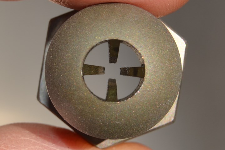
IMC’s novel injection nozzle tip (available from Progressive Components) has internal heat-sink fins to cool the center of the melt channel and prevent strings. Sand-blasted finish reportedly ensures a better seal against the sprue bushing.
No Strings Attached
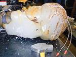
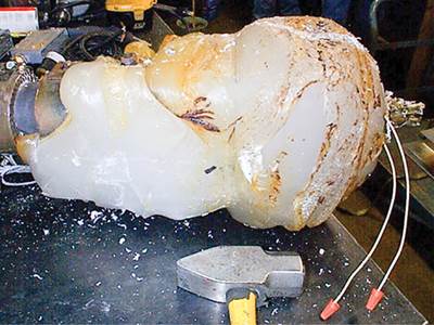
As Fattori explains, stringing results when the center of the slug of plastic inside the machine nozzle-tip orifice has not sufficiently solidified when the mold opens. When the part is ejected, it drags thin strings of still-molten plastic after it. Those strings tend to be static charged and therefore stick to the mold. If they hang over the parting line, those thin strings of plastic will hob the mold—even a heat-treated steel tool—eventually leading to flashing. Fattori says that can’t be fixed properly by simply grinding the parting line—it requires an extensive mold rebuild, “all because of a $20 nozzle tip.” He adds, “I know of one molder that spends thousands of dollars a year on mold repairs due to stringing.”
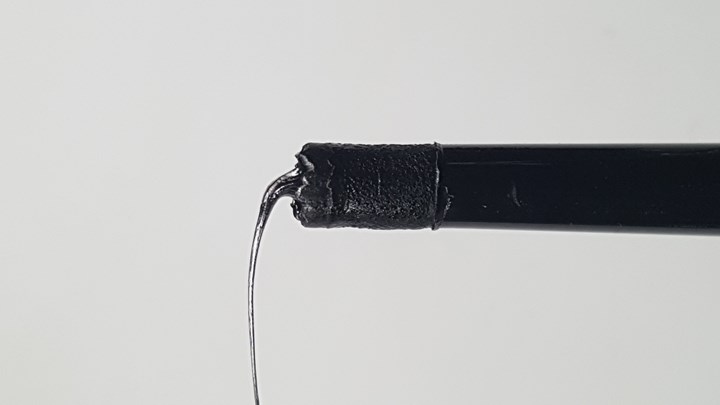
Strings originate at the molten center of the melt channel in a machine nozzle tip, which often does not solidify within a desirable cycle time.
Nozzle tips with large orifices are more prone to stringing because they take considerably longer to become semi-solid—usually longer than the best possible cycle time. Molders have tried various methods to reduce string formation, each of which has its own drawbacks:
• Extending the cycle time, which is economically undesirable;
• Lowering the nozzle-tip temperature, which can increase the risk of cold slugs and nozzle freeze-off, leading to cosmetic flaws in parts and/or to costly downtime;
• Using a smaller nozzle orifice diameter, which increases the pressure drop through the nozzle tip. That increases shear and often requires a slower injection rate to avoid shear burns—adding to cycle time. What’s more, slow injection through a restrictive bore requires higher injection pressure—risking trouble if the machine is close to being pressure-limited;
• Using a nozzle-tip insulator, which Fattori says can be “a royal pain out on the production floor—and most of them don’t work”;
• Using sprue break, which adds to cycle time (a little or a lot, depending on how far the barrel is retracted) and can lead to nozzle drool, leakage between the nozzle and sprue bushing (when drooled material obstructs close contact), and deformation of the nozzle tip and/or sprue bushing from repeated banging together—leading to even more material leakage.
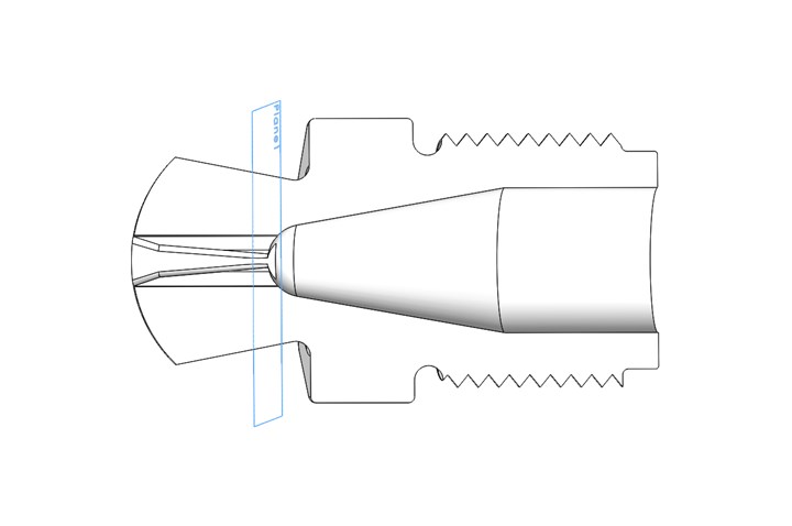
Cross-section of IMC nozzle tip shows tapered internal heat-sink fins, which start at the “transition plane,” which is where the solidified material separates from semi-solidified melt on part ejection. Also shown is the novel profile of the tip, which reduces thermal mass for improved temperature control.
Fattori realized that the solution to the problem was to get more cooling into the center of the flow channel in the nozzle tip. He came up with the idea of adding inwardly protruding, heat-conducting metal fins inside the bore of the nozzle tip. These fins are angled, with their maximum height 70% into the melt stream, with their peak at a location Fattori calls the “transition plane” inside the nozzle tip, which is where the molten material will separate on part ejection from the semi-solidified plastic. From this plane, the fins taper down to blend with the front orifice diameter. This taper concentrates the cooling at the transition plane, which flow simulation shows is the area where the greatest concentration of thermal gradients occurs inside the nozzle. The temperature differential between the sprue-bushing nozzle seat and the transition plane was found to be as high as 135° F in the simulations. Using fins to concentrate the cooling at the transition plane ensures the separation point is consistently in the same location, which results in repeatable shot sizes, Fattori adds.
Nozzle strings can force an extensive mold rebuild—all because of a $20 nozzle tip.
Fattori also notes that as plastic cools inside the nozzle tip, it shrinks away from the inner bore surface, which reduces the rate of heat transfer. But the fins are always in contact with the melt and are in close proximity to the center of the melt stream, increasing the effective cooling rate.
The new tips have eliminated stringing in tests with PS, HDPE, LDPE, PP, PVC, ABS, ASA, acrylic, nylon, acetal, PC and PPS (filled and unfilled). However, Fattori cautions that “these new IMC nozzle tips are only to be used on molds with a stringing problem, or molds for which you cannot reduce the cycle time without having a stringing problem. The new nozzle tips are so efficient at removing heat that they can cause a freeze-off condition, particularly on the smaller orifice sizes.”
Fattori concedes that the thin fins inside the IMC nozzle will tend to wear, especially with filled materials and/or high injection speeds. Wear will gradually reduce the fins’ effectiveness at heat transfer. “Some tips have been running for over a year now with minimal wear,” Fattori comments. “But let’s say you’re running 33% long-glass filled nylon and you have to replace the tip once a month—that’s still a lot cheaper than having to literally rebuild the mold.”
Other Tip Design Improvements
According to Fattori, “A nozzle tip undergoes both a constant and cyclical thermal battle. It is heated in the back half by the machine’s nozzle body. It is cooled in the front half by contact with the sprue-bushing seat and by convection into the atmosphere.” These opposing thermal forces are fairly constant and come into equilibrium over time. But, he notes, that equilibrium is upset by the substantial heat generated during each injection cycle from frictional shear of the material.
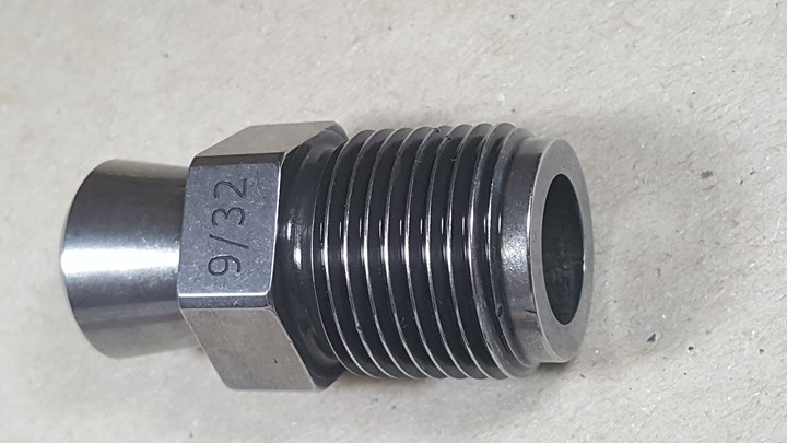
IMC nozzle tips are made of 420 stainless steel, which is harder than the typical H-13 steel. A simple but helpful added feature is the orifice diameter engraved on the wrench flat, unlike most nozzle tips, so no measuring tool is required.
As a result, Fattori states, “A nozzle tip must be able to react quickly to temperature changes, so as to prevent formation of strings within the best cycle time.” That requires efficient heat conduction to remove excess heat from the nozzle tip. But rate of heat conduction is affected by the mass of the object: Greater mass slows heat transfer. In Fattori’s view, “Every standard nozzle tip today has a very large mass. It begins at the back side of the wrench flats and extends all the way to the front face of the tip.”
The new IMC nozzle tip incorporates four features to greatly increase the rate of heat transfer to compensate for momentary temperature rises:
1. The thick mass in the front was replaced with a contoured outer shape that corresponds to the internal geometry, with the smallest diameter at the transition plane.
2. The transition plane is located roughly 1/8 in. forward of the massive wrench flats.
3. The overall length of the nozzle tips varies in order to vary the land lengths: The larger the orifice, the longer the land to increase thermal conductivity. If the land lengths were all the same, tips with small orifices would be more susceptible to generating cold slugs, and tips with large orifices could string under almost any condition.
4. Diameter of the nozzle-tip face is reduced to decrease the amount of contact area between the face of the tip and the sprue-bushing seat. Other nozzle tips, with their large contact area, are greatly affected by how well, or how poorly, the sprue bushing is cooled. Since every mold is different, these nozzle tips can behave inconsistently from one mold to another. Fattori points out that the reduced contact area also results in greater sealing pressure for the same nozzle touch force, preventing carriage blowback and nozzle leakage.
You don’t have to physically measure the orifice on an IMC tip to know its size—it’s engraved on a wrench flat.
The IMC nozzle tips are available with a ½-in. spherical radius, in eight different orifice sizes of 5/32 in. through 3/8 in. in 1/32-in. increments. Fattori says the bore diameters of the IMC nozzle tips are slightly smaller than their nominal size. But even with the internal fins, the resulting flow area is comparable to most “full-flow” style nozzle tips. He also says that his tips’ large internal transition radius “virtually eliminates ‘dead spots’ where material can stagnate.”
According to Fattori, most nozzle tips are made of H-13 steel with a Rockwell hardness of 46 to 48 Rc. IMC tips are made of 420 stainless steel with a vacuum bright hardness of 48 to 52 Rc for greater durability.
Some tips are highly polished. IMC tips are lightly sand blasted, which Fattori says produces a better seal.
One more innovation is very simple, but nonetheless valuable to molders. Fattori explains, “For some reason, you have to physically measure the orifice of most nozzle tips with some kind of tool in order to know their size.” He solves that by engraving the orifice size of each IMC nozzle tip on a wrench flat.
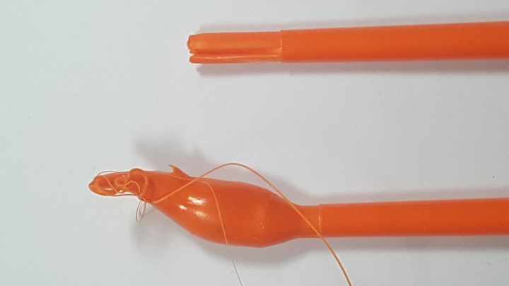
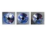
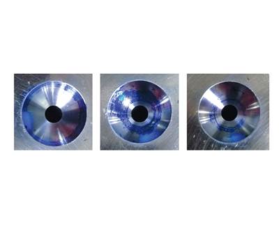
Real-world testing (here with ABS) confirms that the IMC nozzle tip (top) eliminates stringing, regardless of the orifice size or material type.
The IMC nozzle tips cost more than other tips, because they cost more to make. “But the ROI on any mold that has an extended cycle time to overcome or reduce a stringing problem is typically just a few days,” Fattori asserts. “And the money saved from not having to repair just one mold due to string damage can probably pay for a year’s supply of IMC nozzle tips.”
One more thing: Fattori says, “In case you were wondering, the internal heat-sinking fins have also proven to work well in hot sprue bushings and in hot-runner systems.”
Related Content
PHA Compound Molded into “World’s First” Biodegradable Bottle Closures
Beyond Plastic and partners have created a certified biodegradable PHA compound that can be injection molded into 38-mm closures in a sub 6-second cycle from a multicavity hot runner tool.
Read MoreNPE2024 Wrap-Up: Sustainability Dominates Show Floor News
Across all process types, sustainability was a big theme at NPE2024. But there was plenty to see in automation and artificial intelligence as well.
Read MoreScaling Up Sustainable Solutions for Fiber Reinforced Composite Materials
Oak Ridge National Laboratory's Sustainable Manufacturing Technologies Group helps industrial partners tackle the sustainability challenges presented by fiber-reinforced composite materials.
Read MoreAutomotive Awards Highlight ‘Firsts,’ Emerging Technologies
Annual SPE event recognizes sustainability as a major theme.
Read MoreRead Next
How to Prevent Nozzle Tip Leaks, Part 1
Instead of learning from your mistakes, stop making them in the first place.
Read MoreHow to Prevent Nozzle Tip Leaks, Part 2
Your very costly mold in that very expensive press is relying on the performance of a $20 nozzle tip that no one ever checks, and has a high probability of not doing its job. Stop learning from your mistakes and start learning how not to make them.
Read MoreNozzle Leaks: Why They Occur, How to Detect & Fix Them
Nozzle leaks are a serious problem in injection molding. Here are some causes and remedies.
Read More


