The Scoop on Blow-Pin Stands, Pre-Pinch Units & Parison Spreaders
Spend time to identify the right accessories.
Most processors spend a lot of time defining what should be included in their new blow molding machine. Yet a precious few spend any time identifying the need for a blow stand and accessories. Few of these machines are supplied with blow stands by the builder. As a result most of them are home-built, poorly designed, inflexible, and unstable. Most often, the basic blow stand is made to serve limited functions such as blow-pin up/down and air on/off.
Other functions such as pre-pinch/pre-blow and parison spread are usually put on the bottom blow frame in order to become part of the basic blow stand. The parison spreader is normally used in conjunction with the pre-pinch. Again, these are hit or miss mountings and have limited flexibility for proper use during the parison forming.
Here are some explanations for using each of these functions:
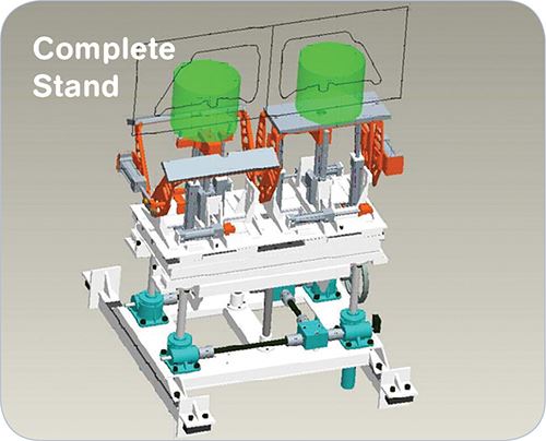
•A bottom blow stand unit is used for mounting the blow-pin assembly, pre-pinch unit, and parison spreader unit. The stand is used for manual setups during mold changes and setup requirements. Motorized control allows for rapid and accurate up/down position changes. This manual up/down movement should be in the maximum range of at least 17 in. total adjustment.
In addition, the blow-pin cylinder will have a rod stroke of 12 in. to add to this total adjustment. The blow stand should be very flexible and allow rapid changeover of the other functional components. This bottom stand unit has many threaded holes in the top mounting plates for proper positioning of the components. The system utilizes four vertical jacks with couplings and shafting between each jack unit. Miter boxes are also used to allow proper up/down movement of all four jacks. This becomes a very stable frame to handle the forces created during the neck compacting functions.
•The blow-pin assembly allows the parison forming air to enter the parison from the bottom of the mold. Normally, the stroke of this vertical hydraulic cylinder is at least 12 in. The blow pin also forms the neck opening in the molded part. It requires water cooling. Depending on the part requirements, the neck opening could be compacted for a sealing or finished surface in the part. This can be accomplished by having a secondary position or midpoint, and the blow pin will move to this position at full mold closing. Once the mold is closed, the vertical cylinder is fully extended. This stroke will move a small distance (0.020 to 0.050 in.) to the final, fully extended (upward) compacting position.
These positions can be identified with either proximity switches or more precise linear potentiometers. Some parts may require even finer finishes to be provided as a secondary operation.
Once the mold starts to open, the bottom blow pin is used to help demold the parts from the cavities on the bottom, along with the takeout device gripping the upper portion of the parts. After a small movement of the platens, the blow pin is retracted completely from the mold cavity to allow the takeout device to remove the part from the press. Blow pins can also be used as spreaders. For example, with 55-gal drums, blow pins in both openings can spread the parison and then would have an unspin device if internal threads were molded into the ID of the neck.
•A parison pre pinch unit uses two water-cooled aluminum plates in either a bear-trap or horizontal-closure arrangement. Either type of unit is normally used in conjunction with a needle-blow setup. The parison is pushed out, and at the end of the cylinder stroke (accumulator empty) the two pinch bars will close and seal the parison on the bottom. Preblow air then inflates the sealed parison. The preblow air will shut off when the clamp is closed. At this time, main blowing air will be introduced by a needle that is injected into the parison.
Pre-pinch units can also expand or restrict the layflat range of a given size of head tooling. This saves setup time for changing head tooling.
Some pre-pinch units are mounted directly under the mold halves. But if a large blow-up is required, the distance between mold halves most likely will not be big enough to inflate the parison without it hitting the mold.
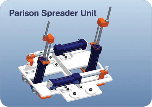
•Parison spreader units are ideal for making blow molded panels. Two spreader pins will ensure that the parison width will be at the same desired position cycle after cycle. It will also prepare the parison for the wide, flat part shape, which is usually 2 in. to 3-in. thick. It will also tend to move the thin wall of the parison into the flash pocket of the mold and not in the actual part.
Spreader pins also work well when used with the pre-pinch unit. The spreader pins can be used under or over the pinch plates. If used over the plates, notches must be cut into the face of both pre-pinch plates to make room for the spreader pins. You will also need to pay attention to minimum and maximum postions of the stroke of the spreader plates.
It is important to have a copy of the mold cavity drawing to ensure the proper relationship between all the blow-stand positions and the various cavities. Most likely, each mold will have a different width, length, and height. Hence, the setup adjustment range for all molds must be examined. This is extremely important when using a compacting blow-pin arrangement.
It is worth the time to establish the range of parts and molds to be used on a given machine. This examination will help determine the parison size required to make a given part and it will also identify any obstructions preventing a straight parison drop or that could hit into the mold cavity.
Some parts will require a diagonal movement of the blow pin of up to 4 in. or so for offset neck openings. This requires several adjustment positions and moving plates. In some cases, blow pins are set at a 45° angle to the parison. This also needs several different set positions to allow the parison to drop over the angled blow pin and not hang up prior to reaching its final length.
Pre-planning is necessary make this difficult process achievable in production. In most respects, this will not be accomplished in the first parison drop. It could take several hours to make all the adjustments needed for an acceptable part.
The design of the lower blow stand must allow fast part changeovers. Changeover can be well within 30 min using simple lock-down methods and quick disconnects for electrics, air, water, and hydraulic hoses. Fine mounting adjustments are also achievable with the four lock-down bolts on the lower blow stand.
Related Content
Why Shoulder Bolts Are Too Important to Ignore (Part 1)
These humble but essential fasteners used in injection molds are known by various names and used for a number of purposes.
Read MoreInjection Molding: Focus on these Seven Areas to Set a Preventive Maintenance Schedule
Performing fundamental maintenance inspections frequently assures press longevity and process stability. Here’s a checklist to help you stay on top of seven key systems.
Read MoreThree Key Decisions for an Optimal Ejection System
When determining the best ejection option for a tool, molders must consider the ejector’s surface area, location and style.
Read MoreThe Effects of Stress on Polymers
Previously we have discussed the effects of temperature and time on the long-term behavior of polymers. Now let's take a look at stress.
Read MoreRead Next
Beyond Prototypes: 8 Ways the Plastics Industry Is Using 3D Printing
Plastics processors are finding applications for 3D printing around the plant and across the supply chain. Here are 8 examples to look for at NPE2024.
Read MoreMaking the Circular Economy a Reality
Driven by brand owner demands and new worldwide legislation, the entire supply chain is working toward the shift to circularity, with some evidence the circular economy has already begun.
Read More
