Get Better at Multi-Material Molding
Since each multi-material application is unique, there’s no standard best method for success. Each molding solution must be tailored to meet the needs of the final product.
Multi-material molding is a common way of forming products that require characteristics one material alone just can’t provide. It’s often used to give added aesthetic appeal, stability, functionality, or marketability over traditional designs. Common examples include automotive taillights, toothbrush handle grips, seals, gaskets, and a variety of other products.
The unique needs of each application usually drive demand for multi-material parts, and molders have many options for production techniques. Since each multi-material application is unique, there’s no standard best method for success. Each molding solution must be tailored to meet the needs of the final product.
Multi-material molding is a complex process and can add cost, cycle time, and other challenges to a project. Ultimately, the value it adds must outweigh the additional effort (and cost). While there’s a learning curve for entry, with the right knowledge and support, any molder should be able to provide this service.
This article will offer you a look at things to consider when approaching a multi-material project. It will also provide an overview of multi-material molding options and the benefits and optimal applications of each.
INITIAL CONSIDERATIONS
One of the most important considerations before starting a project is determining whether multi-material molding is the best solution for your application. There are a variety of other techniques that can produce similar results. Components can be bonded or mechanically attached in post-production, or part designers can incorporate other material and design alternatives in the development stage.
It’s important to evaluate each application for cost and practicality. Generally, higher production quantities can offset the cost of multi-material molding, making it a more attractive option. For shorter runs, automated or manual assembly and other solutions are often more cost-effective.
If multi-material molding is the best route, early and constant collaboration is key. To ensure the mold(s), materials, and machines work as efficiently as possible, designers must rely on the expertise of their partners. The best parts are produced through a joint effort of a part designer, tool designer, material supplier, processor, and machine engineers—all in constant communication from the earliest development stages. Through cooperation, many common molding pitfalls can be avoided and a better, more effective, and more cost-efficient part results.
One of the next steps in the process is material selection. Compatible chemistries and shrink rates are important considerations. Some materials bond well, some bond adequately for certain applications, and some don’t bond at all. There are many available charts that show relationships between materials. These can serve as general guides, but given the thousands of materials available, be sure to work closely with your material supplier for the best results.
It’s also not unusual to mold more than two materials, and some applications call for numerous colors or resins. However, since only 10% of the applications involve more than two materials, we’ll focus on two-material molding in the remainder of this article.
OPTIONS FOR MULTI-MATERIAL MOLDING
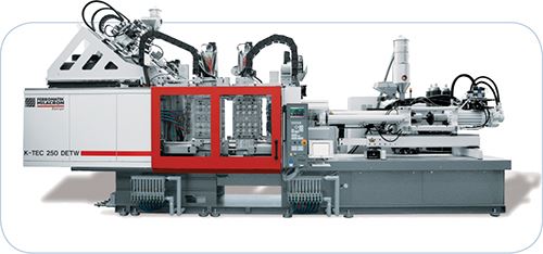
There are two major types of multi-material molding. The names vary throughout the industry: What one plant calls overmolding another calls two-component and yet another, co-injection. For this article, we’ll define the two general approaches as sandwich molding and overmolding.
Sandwich molding, which is generally done for cost-reduction or strength-enhancing purposes, involves molding an aesthetic surface layer of one material over a core of a different, usually less expensive or more rigid material. It’s accomplished with two injection units filling the same mold cavity at almost the same time. When done properly, you wouldn’t be able to tell the part contains multiple materials unless you were to cut it open. The sandwich molding method works very well only for a small number of applications.
Overmolding provides more options than sandwich molding. Overmolding occurs by molding the first material into a shape, and then molding a second material over it in a separate process.
There are two basic ways to accomplish overmolding. One way is to mold the initial part, manually or robotically remove it, place it into another mold in another machine, and then inject the second material. Switching molds this way can be time consuming and labor intensive. Contamination can be an issue, and it’s difficult to register the part back into the tool as precisely as necessary every time. So when using this method, it’s important to incorporate locators into the part to help line it up correctly in the mold. It’s also important to consider and account for the shrinkage of a part that occurs when removing it from one machine and moving it to another. Too much shrinkage can lead to improper seals in the new mold cavity and part imperfections.
The two-machine method is less common today than it was in the past, but it does offer greater flexibility and the ability for molders to use existing machines or smaller machines. Because overmolding doesn’t require specialized equipment, molders can get into the market more quickly this way.
The more common—yet more complex—way of overmolding is to use just one machine with a rotary core. This means the machine must be large enough to accommodate the core and incorporate multiple injection units, but the approach still has a number of advantages over the two-machine method.
There are a number of ways to accomplish rotary core overmolding, and we’ll discuss four of them here: turning plate, turntable (rotary platens), core back, and stack turning.
Depending on the specifics of your application, each of these options has different benefits and carries greater or lower costs. Sorting through these circumstantial differences to determine the method that will maximize performance, quality, and cost-effectiveness is another reason it’s important for part and mold designers, processors, material suppliers, and machine providers to work together from the beginning of a project.
TURNING PLATE
Turning plates are used when trying to mold the same material on both sides of a parting line and completely encapsulate a portion of a part, for example, surrounding the handle of a toothbrush with a second material.
Turning plates require the use of two different cavities and cores. This operation functions by molding the initial component, opening the mold, and moving the part into a second cavity by means of the turning plate moving on a horizontal axis. The mold closes. The machine injects the second material to create a finished part, while simultaneously injecting another initial component in the first cavity. The finished part is ejected from the second cavity. The turning table moves the new initial component into the second cavity, and the process repeats.
One major advantage of turning plates is that they offer quick cycle times, since the injection of both cavities is parallel. While turning plates usually produce good part quality, the technology limits the number of cavities, and therefore parts, a processor can run at one time.
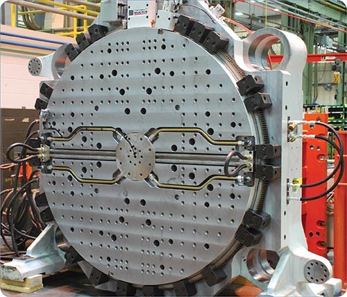
TURNTABLE (ROTARY PLATENS)
A turntable is similar to a turning plate, except that instead of the plate turning, the B side mounting surface rotates the mold, usually 180°. This allows half of the mold surface (the A side) to be used for part production. The B side remains on the core and is not open for the second material.
This method requires a mold to be located directly in the center of the turntable, both vertically and horizontally. It will be important to incorporate a locating device, such as pins or keys, to ensure that the part is lined up correctly when the table rotates to fill the second cavity. The table can also be set up to accommodate more molds or to oscillate instead of completely rotating. Almost all turntables are servo driven, making them very precise and additionally helping with this critical centering action.
Turntables are a good option for producing parts like multi-colored washing-machine agitators. Multiple colors can enhance marketing appeal and value, and the higher price point of these parts can justify the increased production cost.
CORE BACK
The core back is used when you need to pull a core out of a mold before injecting the second material. Seals and gaskets often use this method. The initial component is molded and cooled, the core is pulled back, the second material is injected into the volume exposed by the retraction of the core, the part is cooled and then ejected.
Core-back molds generally cost less and allow a moldmaker to incorporate a high number of cavities into a tool. This process does have longer cycle times, since it requires injection of one component after another and two separate cooling cycles.
STACK TURNING
Stack turning can be used for either single stacks, two single-face molds mounted back to back, or cubes—four molds all mounted on a cube. This method enables a molder to use the full mold surface for each shot, which doubles the output and balances the clamping and injection pressure. It also incorporates parallel movements for reduced cycle time.
This technology is commonly used when speed and volume are critical factors. A common application of stack turning is for production of bottle caps with a liner on the inside and another material on the outside.
Single stacks turn 180° along a vertical axis, doubling the number of cavities with the same clamp force compared with previous methods. The mold can generally turn in as little as 1.3 to 3 sec. It’s ideal for heavy molds, and can use standard stack technology in the same system.
Stack-turning technology with a 90°-turn cube system provides excellent access to the mold and makes in-line assembly possible. The cube method reduces cycle time, which in turn reduces production cost for high-volume runs.
MACHINE CONFIGURATIONS
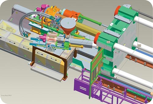
As specified earlier, the size and tonnage of a machine will be dictated by the size of the tool. After a machine is selected, you have to determine the best location for the second injection unit, which will help guide the machine configuration. Here are four of the most common configurations:
•Parallel: This method has side-by-side injection units located in holes that go through the platen. However, these two holes limit the machine from being used for anything other than multi-component molding. Another solution when parallel injection is needed is to have one injection unit utilizing the central hole as in a traditional molding setup and running a small hot runner through the platen in a second, smaller hole, interfacing with the tool mounted on the other side. In this instance, the second injection unit is positioned at an angle that allows for the machine to be used for more than just parallel, two-component molding. Both configurations of parallel molding use relatively little floorspace.
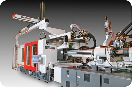
•Perpendicular: This is probably the most common machine setup, and is middle-of-the-road in terms of cost. The second injection unit is located off of the back—non-operator—side of the machine. It takes up more floorspace but allows for easy robotic removal of the part from the top.
•Vertical: This method has a small footprint and is ideal when smaller injection units and shots are needed. It is also limiting in terms of robotic part removal, so a part-drop ejection is best.
•Over/under: This method is parallel injection with the second barrel injecting over the top of the fixed platen. Two major benefits of this configuration are that it’s compatible with top-entry robotics and that the main injection unit doesn’t have an altered location, meaning the machine can also function with a conventional single-material mold.
Having the proper sequencing will lower cycle times and make the production process as efficient as possible. With a rotary table, where the cavities are independent, both materials can be injected at the same time. Both injection units will start together, but whichever unit has the longest process will determine the cycle time. If the cavities aren’t independent—as with a core back, for example—the sequence will need to be adjusted.
Most newer machines have control software that can handle the extra inputs and outputs associated with multi-material molding. But be aware that this is not always the case. Some older control systems or low-level controls on retrofitted machines might not be able to accommodate your requirements. Talk to your machine supplier to ensure everything is up to par.
Multi-material molding comes with a variety of challenges, but it’s a field almost any molder should be able to enter with a little bit of knowledge and network of support. There are many options and each application is unique. There’s no one best solution for all applications, so it’s important to work closely with a qualified moldmaker, molder, machine manufacturer, and material supplier to ensure you have best setup for the part you’re trying produce
Related Content
Bozzelli’s Guide To Specifying a Dryer
Here's a list of 17 things to do when looking for new drying equipment.
Read MorePlastics Technology Year in Review: Your Favorite Reads of 2024
A year-end review of the top stories showcasing industry trends, advancements and expert insights. Revisit the articles that captured the attention of the plastics community.
Read MoreMedical Tubing: Use Simulation to Troubleshoot, Optimize Processing & Dies
Extrusion simulations can be useful in anticipating issues and running “what-if” scenarios to size extruders and design dies for extrusion projects. It should be used at early stages of any project to avoid trial and error and remaking tooling.
Read MoreUltrasonic Welding: Tips, Techniques, and Troubleshooting
In this collection of content, we provide expert advice on welding from some of the leading authorities in the field, with tips on such matters as controls, as well as insights on how to solve common problems in welding.
Read MoreRead Next
Beyond Prototypes: 8 Ways the Plastics Industry Is Using 3D Printing
Plastics processors are finding applications for 3D printing around the plant and across the supply chain. Here are 8 examples to look for at NPE2024.
Read MoreSee Recyclers Close the Loop on Trade Show Production Scrap at NPE2024
A collaboration between show organizer PLASTICS, recycler CPR and size reduction experts WEIMA and Conair recovered and recycled all production scrap at NPE2024.
Read More
