Keep Extruder Barrels Aligned…And Production on Target
A misaligned barrel causes a lot of trouble. Laser alignment is being used now to keep things on the straight and narrow.
What happens when an extruder barrel becomes misaligned? A lot of bad things. For starters, the screw, barrel, and even the gearbox will experience premature wear. Then a falloff in efficiency will follow, as rapid wear increases the diametric clearance between the screw flights and the barrel. In extreme cases, misalignment leads to catastrophic failure, as components undergo so much deflection that the screw either breaks outright or forms a metal-to-metal adhesive weld with the barrel so that the extruder seizes up.
So how do you prevent all these headaches? First, understand that barrel misalignment is measured with respect to the rotation axis of the extruder drive quill. In other words, a perfectly straight, brand-new barrel can still easily be misaligned to the rotation axis of the quill, with potentially ruinous results. One common, lingering misconception is that alignment can be indicated by use of a level. Not so; this measures only the levelness of the outside of the barrel, which has virtually nothing to do with the alignment of the barrel centerline relative to the rotation axis of the extruder drive quill.
There are two typical types of misalignment:
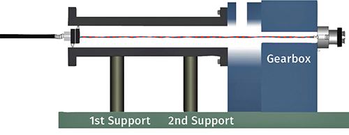
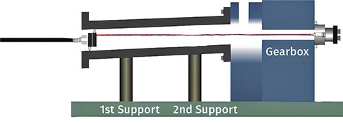
1. Radial misalignment: This occurs when a barrel is mounted parallel to the quill’s rotation axis but is offset radially, causing interference between screw and barrel along the entire length.
2. Angular misalignment: This occurs when a barrel is centered to the quill’s rotation axis at the mounting surface, but slopes up/down or left/right relative to the quill’s rotation axis, causing progressively worse interference and wear on the barrel and screw in the downstream direction.
To accurately measure the degree of misalignment and monitor the progress of returning to alignment, until recently the most common method was to position a bore scope to the rear of the gearbox and adjust it so that it optically represents the centerline of the drive. Inside the barrel are one or more transparent work targets with crosshairs.
Looking through the bore scope, you can measure deviations from the centerline and determine how much to adjust the positions of machine components in order to return the system to alignment. You can continue using the scope and work targets to monitor the progress through various stages of adjustment.
Today, laser-alignment systems have largely replaced optical methods. Such systems can be purchased, or technicians can be hired to carry out laser alignment. The accuracy of laser- alignment systems is typically two to three times better than the bore-scope method. Laser alignment also cuts alignment times in half and reduces the likelihood of human error.
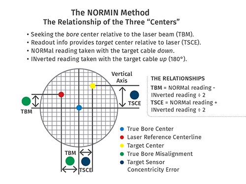
The laser is mounted into the gearbox through-hole (counter-bore) by using a self-centering chuck, which has a specially adapted plate that is centered to the feet to within 0.0005 in. (0.0127 mm). In a simple procedure, the laser is aligned to the quill’s rotation axis and is then projected down into the extruder barrel. The axis of rotation of a spindle is the line around which the chuck or tool holder rotates onto a two-axis self-centering target located at the end of the barrel. This procedure is called NORMIN (Normal-Inverted) and was developed by Hamar Laser, Danbury, Conn. (hamarlaser.com) to compensate for laser or target mounting errors in bore or spindle alignment.
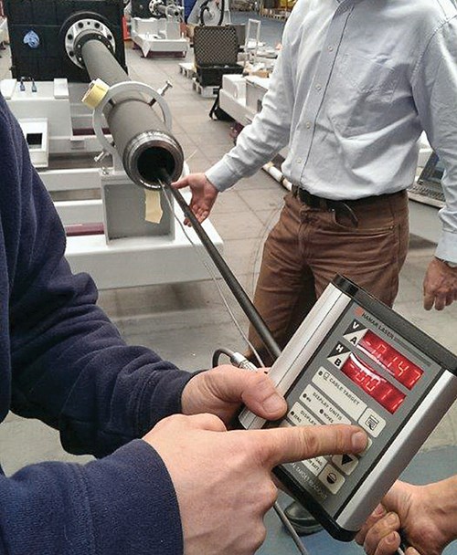
The two-axis bore target and self-centering bore adapter are designed to find the center of the bore, without any moving parts, to a tolerance of 0.0005 in. or 0.0127 mm (with care, tolerances of 0.0002 in. or 0.005 mm can be achieved). A two-axis digital readout is attached to the target to produce X-Y alignment reading and a 5-ft pole (with optional 5-ft extensions) is attached to the target to insert it deep into the barrel so a full measurement of barrel straightness can be taken if desired.
The alignment reading produced after completing the NORMIN procedure is a measurement of the misalignment of the free end of the barrel relative to the quill’s axis of rotation. To align the barrel, it’s best to move the target into the barrel just above the fixed barrel support. The barrel can then be shimmed or moved, while alignment values on the readout automatically update, until it displays zero in both axes. Barrels with multiple supports must be checked and adjusted if necessary at each support location and then rechecked after adjustment at other support locations.
The alignment procedure should be carried out with the extruder and components at room temperature and the barrel as clean as possible. It is recommended that you align the barrel every time it has been disengaged from the gearbox—whether for installation of a new or refurbished barrel or for system maintenance. This applies to any barrel whose inside diameter is 2.5 in. (63 mm) or larger.
Barrel supports play a critical role in barrel alignment. They must be robust enough to bear the weight of the barrel, screw, and other components and incorporate adjusting mechanisms for correcting misalignment. A poorly designed support can restrict the expansion of the barrel when heat is applied and make it very difficult to properly align it.
Barrel alignment requires an investment of downtime, but the return on this investment is considerable. Processors have reported that barrel and screw life increased by two to three times with proper alignment. Alignment also helps to maintain a high level of productivity and product quality and can save on electrical costs, since a properly aligned extruder requires less torque to turn the screw. With the advent of sophisticated alignment techniques and the availability of outside specialists, these benefits can be achieved for extrusion processes of all types.
ABOUT THE AUTHOR
Mark Colella is the global product manager for Nordson Xaloy, New Castle, Pa., a leading supplier of screws and barrels for extrusion and injection molding. He has previously held the positions of dir. of engineering and manufacturing for Xaloy. Contact: (724) 656-5600; mark.colella@nordsonxaloy.com; xaloy.com.
Related Content
Breaking the Barrier: An Emerging Force in 9-Layer Film Packaging
Hamilton Plastics taps into its 30-plus years of know-how in high-barrier films by bringing novel, custom-engineered, nine-layer structures resulting from the investment in two new lines.
Read MoreDeflection Elbows Eliminate Streamers for Large Film Processor
New elbows eliminate troublesome streamers to increase productivity at leading blown film processor.
Read MoreMaterials Suppliers Team on PFAS-Free Solutions
Baerlocher PFAS-fee process aid passes muster in resin manufacturer’s testing on production-sized blown film line.
Read MoreNew Blown-Film Cooling Technologies Set to Debut at NPE2024
Cooling specialist Addex to roll out new auto-profiling air ring for rotating dies, and new single-plenum air ring.
Read MoreRead Next
Making the Circular Economy a Reality
Driven by brand owner demands and new worldwide legislation, the entire supply chain is working toward the shift to circularity, with some evidence the circular economy has already begun.
Read MorePeople 4.0 – How to Get Buy-In from Your Staff for Industry 4.0 Systems
Implementing a production monitoring system as the foundation of a ‘smart factory’ is about integrating people with new technology as much as it is about integrating machines and computers. Here are tips from a company that has gone through the process.
Read MoreSee Recyclers Close the Loop on Trade Show Production Scrap at NPE2024
A collaboration between show organizer PLASTICS, recycler CPR and size reduction experts WEIMA and Conair recovered and recycled all production scrap at NPE2024.
Read More
