Mold Filling Simulation: What, When, Why, How
Mold-filling analysis is the right direction to go, but if you want to arrive at your destination—good parts and an efficient process—you’ll need to pay attention to all the details and select an experienced professional to do the analysis.
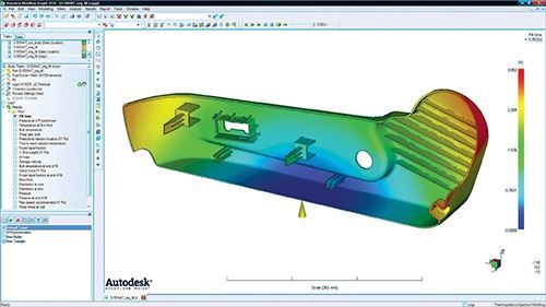
Mold-filling analysis is the computer simulation of molten plastic flow into a given mold geometry. This could be a plastic part, hot or cold runner, gate, nozzle tip, sprue, rib, etc. For a mold, the flow is predicted to the point of 99% filled; packing is a separate simulation. With proper application by an experienced user, this flow simulation can predict—before the mold is built—how the flow front progresses through the flow path of nozzle, sprue, runner, gate, and part. This allows for possible prediction of gate location, fill time, flow restrictions, plastic pressure distribution, air entrapment, venting issues, temperatures, weld lines, and other concerns associated with plastic part production.
Possible is emphasized here because analysis of a virtual process in the computer is sometimes accurate and sometimes not. The software continues to improve, and more advanced programs attempt to simulate packing, warpage, and cooling. This article will focus on only the filling or flow simulation aspects. My perspective on flow simulation is that it is a type of computer-aided engineering (CAE), with the emphasis on aided. The computer can’t do it alone. The software helps an experienced user determine the fill pattern and associated phenomena. Computer software does not have the magic capability to provide good results if the person using it has little or no experience with plastics materials, processing, and tooling.
WHEN TO DO FILLING ANALYSIS
There are two main applications for mold-filling simulation. One is in optimizing a new mold design before steel is cut. The second is solving problems with an existing mold. Both can save lots of time and money.
Designing a new mold: Going from a part drawing to production involves hundreds, perhaps thousands of details. Anything you can do to catch errors in part and tool design upfront will pay huge dividends. Factor in the demand for ever-shorter lead times, ever-increasing part and tooling complexity, and the costs of molds, and it’s obvious that the stakes are high. With the right data (part geometry, material rheology, and processing setup), flow simulation can help avoid costly errors as development proceeds from art to part. The problem is that the simulation has to be done right to provide the cost benefit, and many are not getting the full benefit. My guess is that nearly 80% of all hot runners made by major vendors are designed with flow simulation. (But much of this information never reaches the molder. When buying a hot runner, be sure to ask for the estimated pressure loss, which you’ll need to make sure your machine has enough injection pressure.) My bet would be that about 50% of molds are built with flow analysis. Here are some issues to consider if you have a simulation done on a new mold:
1. Make a list of what is expected of the analysis and decide if the benefits justify the cost. Do you want iterations at different fill times, temperatures, and gate locations? Do you want to know the clamp-pressure requirement? (Note: When a mold has slides, flow simulation generally does not predict the forces projected against the clamp over the heel blocks.) Want to make sure you know weld-line locations, high-stress areas, venting issues, or pressure distribution? Do you need to make sure your equipment has the shot size and injection speed/pressure necessary to mold this part?
2. Make sure there is a commitment within your firm to evaluate and use the report. I have seen too many analyses that are ordered, paid for, and then totally ignored. Worse, it is exceptionally rare that anyone provides or explains the simulation information to the processor before he/she trials the new tool. (Keep in mind that the simulation was performed according to an assumed set of injection conditions. If you run the mold under different conditions, there may be little benefit gained from the simulation.) You should compare the predicted results with actual data once the mold is built. Don’t you want to know if you are getting the benefits of this expenditure or evaluate the capability of the analyst?
3. Be prepared for some hard compromises. The filling analysis may identify an ideal location for the gate from a processing viewpoint, but building a mold with that gate location may be impossible or extremely costly, or the gate location may not be not acceptable from a product performance or aesthetics viewpoint. The simulation analyst should have access to sufficient design information to be aware of such restrictions and should have access to the design team to be able to explore any flexibility allowed in part design and application.
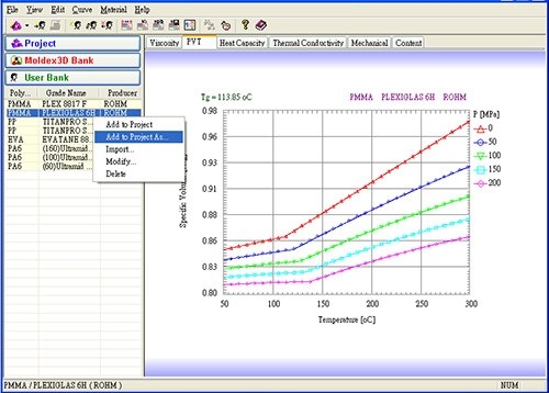
4. Is there good rheology data for this resin? Flow simulation software requires certain material data to predict flow and cooling. If the software materials database does not include your particular formulation (including glass or filler content), using data on an “equivalent” material to perform the analysis may or may not provide accurate results.
5. Can you evaluate the filling analysis on a similar part? The wise user finds an existing mold with a few of the same features of the mold being analyzed (perhaps a similar nominal wall thickness) and does a flow analysis on this mold or section of the mold to show that the software’s predictions correlate with actual molding results on the existing mold. If the software under- or over-estimates fill times, pressures, etc., this data can be used to “correct” the flow analysis for the new mold, providing significantly more confidence in the results.
6. Mold filling analysis alone may not predict cosmetic problems. You may need additional packing, shrinkage, and warpage analysis to predict sinks and distortions.
7. Many simulation programs fall short in predicting the critical balance of filling in multi-cavity tools. It is an unfortunate fact that a “naturally balanced” or “geometrically balanced” runner system will not necessarily produce balanced filling of a multi-cavity tool. If you do not have balanced fill you will not have identical parts. (For details of this discussion see my column in March 2010. Unbalanced filling of supposedly balanced molds has also been explained in numerous articles and papers by Dr. John Beaumont of Beaumont Technology Inc.).
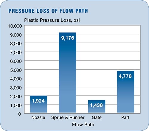
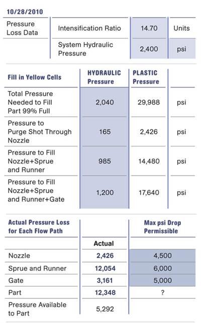
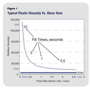
Fixing problems in an existing mold: If an existing mold is not producing good parts or has a high reject rate and an experimental “Pressure Loss” analysis has been done and shows a problem such as that indicated in the accompanying illustration, a flow analysis should be performed. (For a description of Pressure Loss Analysis, see my column in Dec. 2010.) This 20-minute experiment showed that the the sprue and runner were taking up nearly half of the total injection pressure to fill the mold. Obviously something is wrong. While most would simply open up the runner to reduce pressure loss, one actually needs to weigh both sides of the equation. If you open up the runner, pressure will drop to the 4th power relative to the change in diameter. However, the viscosity will increase because the shear rate decreases, and this complicates things significantly. You may win on pressure but pay the price with much stiffer resin. What is the best compromise? Flow analysis is ideal for this situation. First model the flow channel and part, then get the software to match the actual molding conditions, and then do the iterations on channel size to find the best compromise.
WHO SHOULD DO THE FLOW ANALYSIS?
Experience counts. Repeat that 10 times. The ideal analyst has years of experience, not only with the software, but also has shop-floor experience in processing, materials, tooling, and part design. Each of these play a role in flow analysis and affect the quality of the results. Finding someone with this diversity of experience is unfortunately rare, so look for a shop that uses a team of these players to do the flow analysis. Try to find a team that will actually test the results on an existing tool. Request, perhaps demand, that they show you a case history where experiments on the tool matched their predictions.
HOW OT GET GOOD RESULTS:
•Select a qualified team with appropriate experience to do the flow analysis.
•Require at least a 12-layer analysis on complex parts. (Simulation programs “slice” the melt in the flow path into multiple layers and calculate velocities, shear, temperature, etc. separately for each layer.)
•Define and then specify the results you want. No need to waste resources, time, and money on data you won’t use—or on an analysis that doesn’t tell you what you do need to know.
•Make sure you provide the analyst with the correct part/tool dimensions and the current design drawing. And keep the analyst posted on design changes. Also, check to make sure the tool is designed for the correct material shrinkage rate.
•Use a team approach. Involve design, material, tooling, and processing specialists to work with the analysis team.
•If the analyst is using “equivalent” resin data, require him/her to do a check on an existing tool. Volunteer to do this in your shop on a tool you can use as a standard. Actually I would do this for any resin, for what is at stake and the money involved, it is worth the double-check.
•Understand that if you do not request an analysis of the entire flow path, you’ll only get the pressure requirements for what is analyzed. You must add to that the pressure requirements of the nozzle, sprue, runner, etc. Too many processors have come to the unpleasant realization that their machine is pressure-limited. That is, the additional flow paths of sprue and runner maxed out the machine and now the part cannot be filled, or the process runs pressure-limited, providing poor consistency.
•Understand that balance of fill in multicavity molds may not be predicted accurately. Balance of filling multi-cavity molds is critical for identical parts. (See my column in March 2010.)
•Communicate the analysis results to those involved in bringing the tool into production. For example, the flow analysis will usually suggest the fill time for the part. My bet is that this critical number is not passed on to the processor 99% of time. If you do not shoot the tool with the suggested fill time you have essentially wasted your money on the flow analysis. Injection time establishes viscosity; a different fill time will often provide a different part!
In summary, mold-filling analysis is the right direction to go, but if you want to arrive at your destination—good parts and an efficient process—you’ll need to pay attention to all the details and select an experienced professional to do the analysis. Even then, the simulation accuracy may not be on target.
Related Content
Back to Basics on Mold Venting (Part 1)
Here’s what you need to know to improve the quality of your parts and to protect your molds.
Read MoreFundamentals of Polyethylene – Part 6: PE Performance
Don’t assume you know everything there is to know about PE because it’s been around so long. Here is yet another example of how the performance of PE is influenced by molecular weight and density.
Read MoreThree Key Decisions for an Optimal Ejection System
When determining the best ejection option for a tool, molders must consider the ejector’s surface area, location and style.
Read MoreBack to Basics on Mold Venting (Part 2: Shape, Dimensions, Details)
Here’s how to get the most out of your stationary mold vents.
Read MoreRead Next
Injection Molding: Understanding Pressure Loss In Injection Molding
One of the more prominent trends in processing is the need for higher plastic pressures to mold parts.
Read MoreBalanced Filling Is Critical for Holding Molding Tolerances
Processors face a multitude of challenges whenever they approach an injection molding machine.
Read MoreMaking the Circular Economy a Reality
Driven by brand owner demands and new worldwide legislation, the entire supply chain is working toward the shift to circularity, with some evidence the circular economy has already begun.
Read More
.jpg;width=70;height=70;mode=crop)
