Optimizing Thin-Gauge Sheet for In-Line Thermoforming
Processing thin-gauge sheet for in-line thermoforming poses unique challenges. Here’s how to cope with them.
There are operational and financial incentives for a thermoformer to bring sheet extrusion in-house and configure the system for in-line thermoforming of PET, PP, and PS. Double-polished sheet at about 200-microns (8-mils) thick is classified as in the thin-gauge category, and extruding it presents special challenges. This article will examine the key factors that should be considered to run trouble-free thin-gauge sheet extrusion coupled with in-line thermoforming.
RAW MATERIAL CONSIDERATIONS
It is extremely important to deliver melt at a uniform temperature and flow rate in the transverse and machine directions while producing thin-gauge sheet. This requires that variability in the raw-material input be minimized.
Depending on the shape of the part to be thermoformed from the sheet, the process can generate up to 70% regrind. To make the overall process economical, all of the regrind is reused in sheet extrusion. The amount of regrind used and its bulk density affect uniformity of the material input. These variations in raw material can cause head-pressure variations, which should be minimized (±50 psi). The extruder screw should be designed to process bulk-density variations as high as 50% to 100%. In addition, a gear pump, static mixer, and backpressure valve upstream of the gear pump are installed on the line to improve homogeneity of melt that is delivered to the die.
PROCESS REPEATABILITY & STABILITY
The process operating window for thin-gauge sheet production is tighter than for heavy-gauge sheet. For example, non-uniformity in melt temperature delivered to the sheet die can cause premature freezing of melt entering the primary nip point. Any frozen melt entering the nip results in locally uneven surface quality of the sheet due to poor polish.
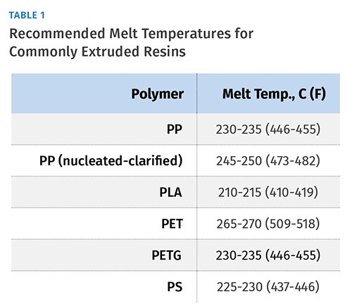
It is important that the melt temperature be uniform within a tight band across the sheet width and over time from day to day to maintain sheet quality. The temperatures in the extruder and downstream components— including melt pipes, screen changer, gear pump, and die—must be maintained within precisely controlled limits. The chrome-roll temperature settings also have to be set high enough to prevent quick freezing on the middle roll. Table 1 lists typical melt temperatures for various materials.
Precise control and coordination of roll speeds is very important to produce high-quality, thin-gauge sheet using different materials. The roll speeds should be maintained within ± 0.05–0.10% of base speed. Poor roll-speed control will introduce undesirable orientation and transverse-direction lines in the form of chatter marks due to uncontrolled stretching of the sheet. Proper tension is maintained in the sheet web by controlling the relative speeds of the main chrome rolls and pull rolls. This tension should be in the range of 2-4 lb/linear in. across the width of the sheet.
MONITOR DIE-LIP TO ROLL-NIP DISTANCE
It is desirable to minimize the distance between the die-lip exit and the primary roll nip, which is typically 4-8-in., depending on line size. This becomes even more important when extruding thin-gauge sheet. Polymer melt leaving the die is exposed to air and tends to freeze off prematurely, which prevents uniform polish in the roll stack. Also, a longer distance to the roll nip can result in excessive neckdown of the sheet width. This can introduce undesirable orientation in the sheet and can create a bead at the edge of the sheet that prevents polishing at the sheet edges and results in higher edge thickness.
Contouring the nose of the sheet die and using a smaller lead-roll diameter helps to bring the sheet die lips closer to the primary roll nip. When external deckles are used, they protrude from the die lip and prevent the close approach of the die. It is recommended that internal deckles be used to control the sheet width, thereby allowing close approach of the die lip to the roll nip.
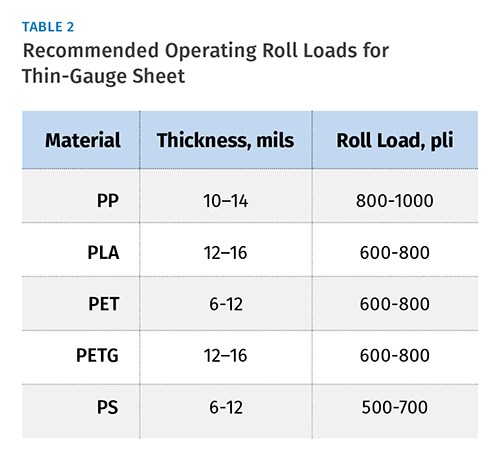
Polishing thin-gauge sheet requires high roll-closing forces. Table 2 lists the recommended roll loads to make high-quality thin-gauge sheet. Running at these high roll operating loads requires appropriately designed and constructed rolls. The tolerances of the roll journal and bearings have to meet tighter requirements. C1 spherical tapered roll bearings are used to provide a total indicated runout (TIR) of 0.0005 in. The overall roll-stand assembly needs to operate while maintaining a precise nip gap under heavy loads that are applied to polish thin-gauge sheet. This also necessitates highly polished roll surfaces, typically at 0.5 Ra or better.
COUNTERACT ROLL DEFLECTION
Due to design limitations, the roll-closing force is exerted on the ends of the rolls where they are supported. As the sheet passes through the roll nip, it exerts a force across the entire width of the roll face. This can cause the roll to deflect under operating conditions. The deflection results in a thick band around the center of the sheet. Since the overall sheet gauge is only 10 mils, even a 2-mil roll deflection will show up as 20% variation in sheet thickness. The target variation in sheet gauge is more typically ± 3%.
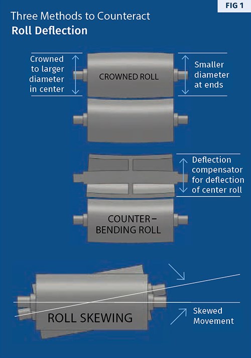
Three methods employed to counteract roll deflection are illustrated in Fig 1. The first is crowning the roll to a larger diameter in the center, which has the effect of compensating for roll deflection in the center. This method works for a specific process and material. However, it does not provide an effective solution when the extent of roll deflection changes.
The second method is counter-bending rolls, which are built with a stiffer construction in the center of the roll. This approach also works at the designed conditions, but has a narrow operating window. Roll-closing forces for this design are limited to 800 pli due to spring-constant and other design considerations.
The third method is to skew the axis of the lead roll by a controlled amount. This preferentially increases roll separation at the edges while keeping it unchanged at the center. By using this technique, the amount of roll skew is matched to the extent of roll deflection at the center. This provides uniform sheet thickness for a wide range of material thicknesses and operating conditions.
MINIMIZE SHEET SAG & DROOP
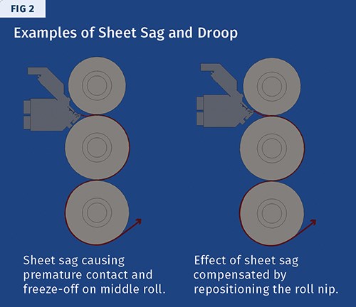
As the melt curtain leaves the sheet die lips, it is critical to introduce it directly into the primary nip without contacting either the lead or bottom roll. Any such contact causes premature skinning of the melt. Subse-quently, the sheet receives an uneven polish and exhibits surface imperfections.
A vertical roll stack is often used due to its applicability to various materials and gauges. As shown in Fig. 2, the rolls are positioned vertically and the melt curtain enters the nip in a horizontal orientation. Gravity causes the melt to sag and contact the middle roll before entering the nip, resulting in partial freeze off of the melt before being polished in the nip. For thin-gauge sheet production, gravity effects of a vertical roll stand configuration are of particular concern. One way to address this is to position the nip slightly lower than the die lip, as shown in Fig. 2.
The J-stack is an alternative configuration of the roll stand. In this case, the melt curtain enters the die lips at a 45° angle to the vertical. This partially reduces the gravity effects and provides additional wrap around the center roll for increased cooling.
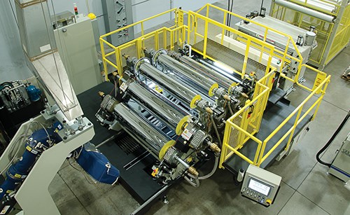
The most effective roll configuration for thin-sheet production is the horizontal roll stand. Here, the melt curtain enters the primary roll nip vertically. Consequently, the unfavorable effects of sheet sag and droop are eliminated. Also, it provides for a wider process window to position the rolling melt bank at the nip entrance against the center roll.
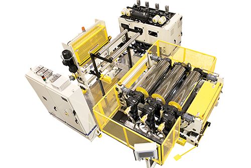
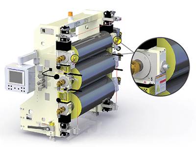
If optically clear, stress-free, thin-gauge sheet is required, as in a PP form/fill/seal application, a roll stand with smaller-diameter multiple rolls provides the best results. PTi’s Super G Multi-Nip Roll Stand has two 18-in. diam. lead rolls and five additional 12-in. diam. rolls, which provide uniform cooling of the sheet across the sheet thickness, resulting in clear, stress-free sheet.
When using a vertical roll stand, an air bar can be installed on the underside of the die to blow air upward against the melt curtain. This helps position the melt bank against the middle roll and minimizes the effects of rapid freeze-off of the sheet before entering the primary nip.
Related Content
What to Know About Your Materials When Choosing a Feeder
Feeder performance is crucial to operating extrusion and compounding lines. And consistent, reliable feeding depends in large part on selecting a feeder compatible with the materials and additives you intend to process. Follow these tips to analyze your feeder requirements.
Read MoreUnderstanding Melting in Single-Screw Extruders
You can better visualize the melting process by “flipping” the observation point so the barrel appears to be turning clockwise around a stationary screw.
Read MoreHow to Effectively Reduce Costs with Smart Auxiliaries Technology
As drying, blending and conveying technologies grow more sophisticated, they offer processors great opportunities to reduce cost through better energy efficiency, smaller equipment footprints, reduced scrap and quicker changeovers. Increased throughput and better utilization of primary processing equipment and manpower are the results.
Read MoreHow Screw Design Can Boost Output of Single-Screw Extruders
Optimizing screw design for a lower discharge temperature has been shown to significantly increase output rate.
Read MoreRead Next
‘Skew’ Rolls for More Uniform Sheet
New feature aimed at thin-gauge PP sheet.
Read MoreLead the Conversation, Change the Conversation
Coverage of single-use plastics can be both misleading and demoralizing. Here are 10 tips for changing the perception of the plastics industry at your company and in your community.
Read MoreFor PLASTICS' CEO Seaholm, NPE to Shine Light on Sustainability Successes
With advocacy, communication and sustainability as three main pillars, Seaholm leads a trade association to NPE that ‘is more active today than we have ever been.’
Read More
