Many polyethylene (PE) film products have a low level of background gels that are considered acceptable for most end users and applications. These gels, however, do not have to be accepted. They exist due to minor design errors in the screw. Screw-design techniques are available that can reduce the occurrence of this type of gel.
The term “gel” refers to any small defect that distorts a film. The low-level background gels at issue here typically do not alarm the quality-control managers in the plant, and as such the film is considered “prime.”
There are many types of gels; these are the most common:
- Highly oxidized polymeric materials that appear as brittle black specks;
- Polymers that are crosslinked via an oxidative process;
- Highly entangled polymeric material that is undispersed but not crosslinked (unmixed);
- Unmelted resin or solid polymer fragments;
- Filler agglomerates from masterbatches;
- A different type of resin or contaminant such as metal, wood, cloth fibers, insects or dirt.
The two types of gels that are the focus of this article are low levels of crosslinked gels and unmixed gels. A crosslinked resin gel is typically formed during an oxidation process, resulting in crosslinking of the resin chains and generation of discolored gels. Highly entangled gels are typically high-molecular-weight polymer chains that are entangled and thus are difficult to disperse during the extrusion process. When analyzed using a hot-stage microscope, the highly entangled gel type will melt as the stage temperature is increased. When the stage temperature is then decreased, the gel will recrystallize, creating the appearance of a gel as a solid polymer fragment. If the gel is exposed to a shear stress right after melting, the stress will often disentangle the chains such that they will not reform when cooled. Since these gels are not oxidized, they are not associated with color. They are commonly referred to as undispersed or unmixed gels.
Troubleshooting PE film extrusion processes where gels are appearing can be difficult due to the number of different types of gels. Because gels can originate from numerous sources, the troubleshooter must be able to identify the characteristics of the gel and recognize the likely source. Process changes must then be performed to mitigate the gel defects.
GELS THAT OCCUR DUE TO ‘MOFFAT EDDIES’
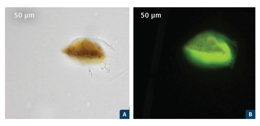
Many PE film processes exhibit a low and continuous level of gels. These are typically oxidized and crosslinked PE material. They occur as black specks and brown soft gels. The gels typically originate from regions of the screw that were stagnant, allowing the resin to have long residence times such that it will degrade.
Photomicrographs of these types of gels are shown in Fig. 2. Typical gel sizes range from 50 to 250 microns. The most common source of these background gels is stagnant regions at the flight radii. The stagnant regions occur because of the formation of “Moffat eddies” that are due to small flight radii.
Troubleshooting PE film extrusion processes where gels are appearing can be difficult due to the number of different types of gels.
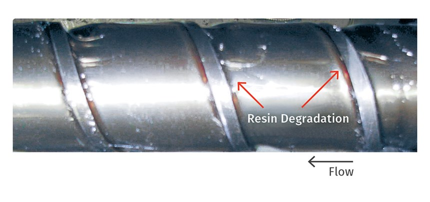
A photograph of a screw with degraded resin at the flight radii is shown in Fig. 3. This degraded material will slowly separate from the screw and contribute to a constant and low level of gels in the film product. The resin will be in the Moffat eddies for extended periods of time, such that antioxidants cannot prevent the degradation.
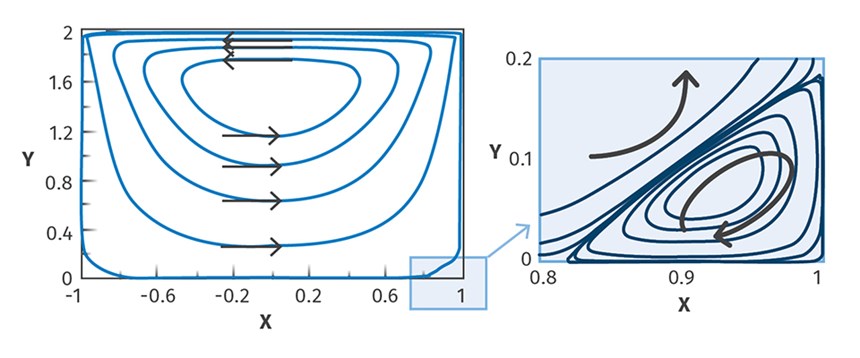
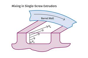
Moffat eddies are recirculations or vortices that occur at sharp corners, as shown in Fig. 4. That is, when fluid is put in motion with top-driven cavity flow, flow circulation is generated in the channel as shown in Fig. 4. A secondary circulation also develops in the corners of the channel, creating a low-velocity helical eddy that is outside the high-velocity flows of the main part of the channel.
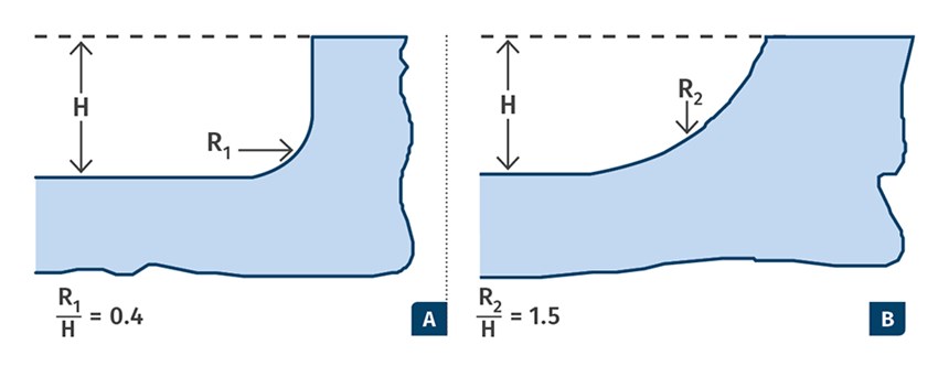
The Moffat eddies that create the degraded resin occur because the flight radii are too small for the depth of the channel. If the flight radii were larger, the Moffat eddies and consequent resin degradation would not occur. Flight radii sizes are shown in Fig. 5. Flight radii that are 1.5 times larger than the local channel depth are recommended for PE resins.
POORLY DESIGNED MADDOCK MIXERS
Poorly designed Maddock mixers are sources for two types of gels that can appear at a low and continuous level. The gel types include thermally oxidized gels, as shown in Fig. 2, and unmixed gels. As stated previously, unmixed gels are highly entangled species that are molten when they are discharged from the die, but solidify first upon cooling to produce a gel that appears as a solid polymer fragment.
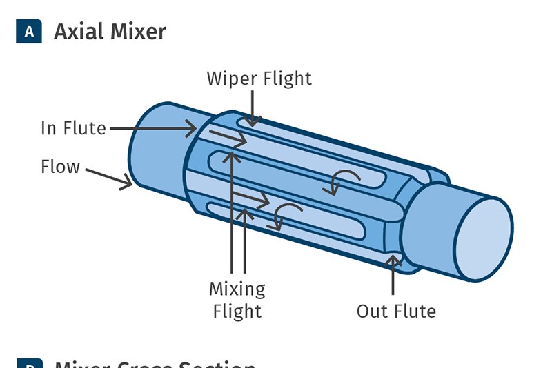
Photomicrographs of an unmixed gel going through the heating and stressing process are shown in Fig. 6. Unmixed gels can be easily removed from an extrusion process by subjecting all molten resin to a one-time high level of stress near the discharge of the extrusion screw. This stress is easily applied using a Maddock-style mixer with a relatively tight clearance on the mixing flight. A schematic of a Maddock-style mixer is shown in Fig. 7. The mixer is designed with pairs of inflow flutes and outflow flutes and a mixing flight with a narrow restriction. The resin flows into the inflow flute. Next, the flow is passed through the narrow restriction created by the mixing flight and the barrel wall. This narrow restriction will disentangle unmixed gels and trap, melt and disperse solid polymer fragments from the upstream melting section. The flow is then passed to the outflow flute and to the downstream sections of the screw.
Poorly designed Maddock mixers are sources for two types of gels that can appear at a low and continuous level.
The unmixed gels are removed from the extrudate by increasing the stress level in the Maddock mixer. The stress level is increased by decreasing the clearance on the mixing flight. The stress level required to disperse unmixed gels depends on the resin and the level of chain entanglement. In past experience, the stress level required to disperse PE unmixed gels is about 100 to 200 kPa. The shear stress that the material experiences for flow across the mixing flight of the Maddock mixer can be estimated using Equations 1 and 2. The shear stress is responsible for breaking up the entangled species. This calculation is based on screw rotation physics.
Equation 1: γΜ= π(Db-2λ)N ⁄ (u+λ)
Equation 2: τΜ = ηγΜ
- γΜ is the average shear rate for flow over the mixing flightin 1/sec.
- N is the screw rotation rate in revolutions/sec.
- η is the shear viscosity at the temperature and shear rate of the mixing process.
- Db is the barrel diameter.
- u is the undercut distance on the mixing flight.
- λ is the main flight clearance.
- τM is the shear stress that the material will experience in flow over the mixing flight.
The preferred Maddock mixer design is atypical configuration except for two features. These include setting the mixing flight undercut to about 0.5% of the screw diameter. Most designs set this undercut at 1 to 1.5% of the diameter. The small undercut specified here will disentangle unmixed gels and trap and disperse all solid polymer fragments that happen to flow out of the melting section. A larger undercut of 1 to 1.5% of the diameter can allow unmixed gels and solid polymer fragments to discharge from the extruder.
The second different feature of the Maddock mixer recommended here is that the depth of the inflow and outflow flutes should be half the width of the flute. If the flutes are made deeper, resin degradation can occur, creating gels in the film product. Maddock mixers with extremely deep flutes and large clearances on the mixing flights are common in smooth-bore extruder designs. In poor designs, the flutes are improperly made too deep in order to reduce pressure consumption in the device. These poor designs will cause resin to degrade at the flute edges, resulting in a low level of gels that contaminate the film product.
WHERE DEGRADATION OCCURS ON THE SCREW
If the gel analysis indicates that the defects are due to degraded resin, then the best way to locate the region on the screw where the degradation is occurring is to remove the screw from the extruder while hot. For this procedure, pellet flow to the hopper is stopped while screw rotation is continued. The screw is rotated until resin flow out of the die stops. Next, screw rotation is stopped and the transfer line is removed from the discharge end of the extruder. The hot screw should be pushed out about three diameters and then photographed and studied for indications of resin degradation. The metal surfaces should appear clean with only mild discoloration. If a stagnant region exists, then dark colored, degraded material will occupy the space.
Once the segment is studied and photographed, the hot resin should be removed from the screw using brass tools. Another three diameters are then pushed out and the process is repeated. If the process is running a natural resin and a colored masterbatch, the extruder should be first purged with the natural resin until the extrudate is essentially free of colorant. The screw shown in Fig. 3 was removed from the extruder using this technique.
ABOUT THE AUTHORS: Mark A. Spalding is currently a Fellow in the Materials & Parts Processing Group at The Dow Chemical Company, Midland. Mich. His expertise is in single-screw extrusion and related polymer processing technologies. Spalding has designed extrusion systems for most of Dow’s major customers for virtually every resin that Dow produces. He is a Fellow and an Honored Service Member (HSM) of the Society of Plastics Engineers (SPE). Contact: 989-636-9849; maspalding@dow.com; dow.com.
Eddy Garcia-Meitin is a technologist leader for Dow in Freeport, Tex. He has been leading optical and electron microscopy efforts towards product development and failure analysis for nearly 40 years.
Stephen L. Kodjie is a senior analytical technologist at Dow in Lake Jackson, Tex. He is an expert in compositional and failure analysis of polymers and has been at Dow for over 10 years.
Xiaofei Sun is a senior engineer in Dow’s Polyethylene Products R&D group in Midland. He is active in troubleshooting single-screw extruders and optimizing Maddock-style mixers.
Gregory A. Campbell is president and chief technical officer at Castle Associates, Jonesport, Me., where he consults on extrusion and polymer processing issues. He taught chemical engineering for 24 years at Clarkson University in Potsdam, N.Y., where he also served as chair of the Chemical Engineering Dept., Dean of Engineering, and University Chief Information Officer.
Timothy Womer is a recognized authority in plastics processing and machinery with a career spanning more than 40 years. He has designed thousands of screws for all types of single-screw plasticating. He now runs his own consulting company, TWWomer & Associates LLC. Contact: (724) 355-3311; tim@twwomer.com; twwomer.com.
Related Content
The Importance of Barrel Heat and Melt Temperature
Barrel temperature may impact melting in the case of very small extruders running very slowly. Otherwise, melting is mainly the result of shear heating of the polymer.
Read MoreSingle vs. Twin-Screw Extruders: Why Mixing is Different
There have been many attempts to provide twin-screw-like mixing in singles, but except at very limited outputs none have been adequate. The odds of future success are long due to the inherent differences in the equipment types.
Read MoreMedical Tubing: Use Simulation to Troubleshoot, Optimize Processing & Dies
Extrusion simulations can be useful in anticipating issues and running “what-if” scenarios to size extruders and design dies for extrusion projects. It should be used at early stages of any project to avoid trial and error and remaking tooling.
Read MoreHow Screw Design Can Boost Output of Single-Screw Extruders
Optimizing screw design for a lower discharge temperature has been shown to significantly increase output rate.
Read MoreRead Next
See Recyclers Close the Loop on Trade Show Production Scrap at NPE2024
A collaboration between show organizer PLASTICS, recycler CPR and size reduction experts WEIMA and Conair recovered and recycled all production scrap at NPE2024.
Read MoreMaking the Circular Economy a Reality
Driven by brand owner demands and new worldwide legislation, the entire supply chain is working toward the shift to circularity, with some evidence the circular economy has already begun.
Read MorePeople 4.0 – How to Get Buy-In from Your Staff for Industry 4.0 Systems
Implementing a production monitoring system as the foundation of a ‘smart factory’ is about integrating people with new technology as much as it is about integrating machines and computers. Here are tips from a company that has gone through the process.
Read More


