TOOLING: The Tool’s Impact On the Molding Process
Flash, venting, cooling, gating, or sticking problems? Better to fix the tool than distort your process.
Having spent the first half of my career building and designing molds and the last half on the injection molding side, I’ve learned that most mold builders do not fully understand the impact the tool has on the production side in terms of part quality and scrap. I was no exception. I had to learn from the “other side” that it’s not just the quality of the tool that determines the success in production. The mold design also has to take into account the specific material and part geometry. That sounds so basic, but I have found that there is usually a gap in understanding, with the process technicians not fully understanding how the tool can impact the process, and the mold builder not fully understanding the process and how the tool design affects it.
Since moving to the molding side, I have always tried to focus on the tool to resolve tough issues, rather than processing around them. Every time you process around one issue your overall process window becomes smaller, putting you at risk for other issues. The focus should always be to understand the root cause of the issue, rather than, “I pushed a few buttons and the problem went away.”
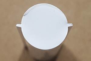
Combating Flash. One issue that many people will attempt to process around is flash. When you process around flash you can put yourself at risk for short shots and other quality issues. Some people will settle for trimming off the flash, which adds extra labor cost and increases the potential for quality issues if flash is not trimmed properly. I have three rules for flash. If all are met, flash is impossible, no matter what material or process is being used.
Rule 1: All mating surfaces are “True Net,” meaning they match perfectly with no gaps or anything holding the parting lines open.
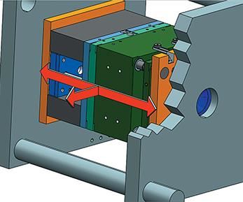
Rule 2: The tool is designed and built robustly enough to minimize deflection in line with clamp force and perpendicular to clamp force.
Rule 3: The clamp force of the machine exceeds the maximum force generated by plastic pressure across the projected area of the cavity and runners.
The latter two rules can often be vulnerable to misdiagnosis. If the tool is proved to have good shutoff with the mating surfaces, you determine which of the last two rules apply. If there is flash in line with clamp force, it results either from tool deflection or lack of clamp pressure. It is important to understand what plastic pressures the cavity is seeing and then multiply by the projected area to determine if you have adequate clamp force.
If the flash is perpendicular to clamp force, it is typically caused by tool deflection and a weak design. When the tool incorporates slides, you need understand the projected area of the cavity surface and make sure the lock angles are designed robustly enough to prevent perpendicular deflection. Inserted lock angles have more potential to move under pressure. The same goes with hydraulic core pulls: Calculateg the cylinder bore size multiplied by the actual hydraulic pressure to make sure it is above the maximum potential plastic pressure, based on the projected area of the cavity surface. Please refer to my series of columns on flash-free molding for a more in-depth look at flash (Oct. 2014 and Nov. 2014).
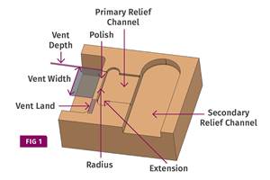
Proper venting. Venting is another area where the tool has an impact on part quality from burns, erosion, shorts, and splay. From my experience over the years, most tools are not designed with adequate venting for a robust process. This is not just an opinion, because improved venting has resolved hundreds of issues. I myself did not understand the importance of venting until I moved to the molding side for maintaining tools. The design of the vent land and vent depth and width along the cavity edge will have an impact on how the vent will hold up or perform. Properly venting details, ribs, and knit lines can drastically improve the process window. This may add cost up front but will reduce maintenance, scrap, and processing time. Refer to my series of columns on venting for a more in-depth look at this topic (May 2015, June 2015, July 2015).
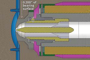
A factor that has a big influence on keeping vents open and reducing the occurrence of parting-line burrs is the parting-line bearing surface. I would use all the bearing surface I could, with no parting-line relief, because there is no disadvantage and only advantages in the production environment. Increased bearing surface will reduce coining because you have more area to absorb the clamp force. Years ago, relief was desired when spotting molds, but with today’s technology the machining takes virtually all the hand work out. So when a tool maker says they need relief to spot the tool, send them my way for a discussion.
I have heard many times the suggestion that parting-line relief provides a better shutoff. There is no logic to that theory and the opposite is true, given the risk of “coining” the parting line. Bearing surface has no impact on flash. Cavity pressure versus clamp force are the only opposing forces.
Gating. This is another important area that has been overlooked. It can affect part quality with unwanted stresses, part scrap, and cycle time. It typically is the most restrictive point in the flow of the plastic but is not always the culprit behind pressure issues. When running into a pressure-limited process, opening the gate does not always have a big impact and can have negative effects on stresses and cycle time related to gate-seal time. Flow length and wall thickness are big contributors to pressure loss in the mold.
And don’t overlook the hot-drop orifice feeding cold runners whenever considering gate changes. Many times, this can be the culprit in pressure loss. I typically promote thinner cross sections and added gate width, but with some materials—such as glass-filled nylons or parts with excessive wall thickness—I recommend larger gate volume to assist with processing and part quality. Gate number and location are also critical with regard to wall-thickness variations in the part, potential quality issues with visual defects, and reducing flow length. For a more on this, read my column on the importance of gate geometry. I will cover this subject more in the future.
Cooling: This is another area that is often overlooked, and the impact it can have is significant. Besides the material and overall part design, areas to focus on are the sprue, runners, and gates. Proper cooling can improve gate-seal and cycle times, and with some materials (like glass-filled nylon) will drastically reduce sprue sticking.
In areas of the cavity that create thin steel conditions, standing towers, or tight areas, don’t overlook the option of using bubblers. These are very easy to design and do not always need cross lines to feed them. I know there is a lot of technology being discussed about cooling with regard to conductive alloys, steel types, and conformal cooling, but I feel that even our standard cooling methods often are not being used effectively.
How small a water line can you use? There really is no limit, as long as water can flow through it. If you think outside the box and use some creativity, you’ll be amazed what you can do with the water design that can have a huge impact on part quality and cycle time. If you are using thermal imaging to assist your process, and are adding cycle time to cool the hotter areas, you should consider what can be done to cool those areas in the tool.
Sticking: These issues are often a result of lack of cooling, improper cavity surface finish for the plastic being used, lack of ejection, or inadequate clearances designed for lifter travel by not compensating for the shrinkage of the plastic. Lifter travel is designed with the depth of the undercut and clearance for part release. But I have seen many times where the amount of shrinkage was not accounted for.
Example: a PP part 20-in. long can shrink as much as 0.400 in., or 0.200 in. from the center to both ends of the part. If the lifter travel was designed with 0.100 in. clearance plus the depth of the part detail, the part after shrinkage could still be engaged in the lifter by 0.100 in., making part removal very difficult or impossible.
Cooling can also have a big impact on sticking with some materials. If your sticking issue shows up or gets worse after the mold has been making parts, and the first shots did not have a problem, cooling should be investigated. Areas with lack of sufficient cooling will retain heat from cycle to cycle and gradually increase in temperature while making parts. In particular, glass-filled materials such as nylon and PPE alloys will need more attention to cooling to reduce sticking and excessive cycle times.
A problem related to sticking is pin push. This can happen with any plastic, but is more prevalent with softer materials. Polypropylene is one material that has created most of the pin-push issues I have dealt with. This can be a result of inadequate polishing on cavity sidewalls, but in most cases it results from inadequate number of ejection pins, size of the pins, or their placement. With softer materials like this, it is not a good idea to locate ejector pins on nominal wall stock near ribs, bosses, or details. If you can put the ejector pins on the bottom of the detail or rib, it will be pushing on a thicker structure than the nominal wall stock.
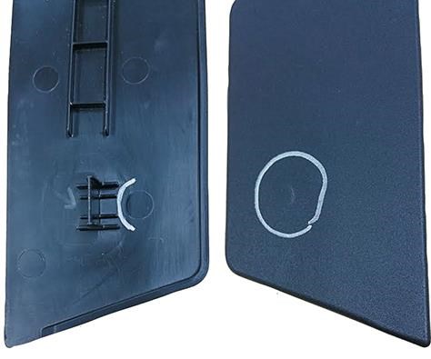
Cavity surface finish can have a big impact on part sticking. In most cases, when a sticking issue arises, the approach is to polish or shine up the problem area. With materials such as PP and polycarbonate, this can make the problem worse. I have seen many cases where I draw polished the highly polished area with 320 to 600 grit paper, and the sticking issue instantly was resolved. I first learned this years ago in a situation where we a tool had been in and out of the mold shop a few times because the part was sticking to the slide details and getting torn. Each time the tool went out of service, it had been polished up and now had a diamond finish. After seeing the situation getting worse rather than better, I made the call to draw polish the shine off because I had no other options to consider without major tool changes. The sticking stopped and was never a problem again.
The same goes with cold sprues, assuming you already have a sprue-puller undercut. On another PP part, the sprue was sticking so hard it actually pulled both cashew gates out with it. An undercut was not going to help if the cashew gates were also getting pulled out. I noticed the sprue was highly polished. Five minutes later, after draw polishing the sprue with 320 paper, we never had a sticking issue again.
ABOUT THE AUTHOR
Randy Kerkstra has been in the plastics industry for more than 26 years, occupied frequently with troubleshooting injection molding. He is currently a tooling manager for a large, multi-plant molding and manufacturing company. Contact:kbmoldingsolutions@gmail.com.
Related Content
How to Design Three-Plate Molds, Part 1
There are many things to consider, and paying attention to the details can help avoid machine downtime and higher maintenance costs, and keep the customer happy.
Read MoreWhere and How to Vent Injection Molds: Part 3
Questioning several “rules of thumb” about venting injection molds.
Read MoreHot Runners: Truths. Myths, Overlooked Areas: Part 2
Here’s a view from the trenches of a tooling manager who, over 30 years, has experienced the joys and pains of using virtually every type of hot runner on the market. Part 2.
Read MoreBack to Basics on Mold Venting (Part 2: Shape, Dimensions, Details)
Here’s how to get the most out of your stationary mold vents.
Read MoreRead Next
People 4.0 – How to Get Buy-In from Your Staff for Industry 4.0 Systems
Implementing a production monitoring system as the foundation of a ‘smart factory’ is about integrating people with new technology as much as it is about integrating machines and computers. Here are tips from a company that has gone through the process.
Read MoreSee Recyclers Close the Loop on Trade Show Production Scrap at NPE2024
A collaboration between show organizer PLASTICS, recycler CPR and size reduction experts WEIMA and Conair recovered and recycled all production scrap at NPE2024.
Read More
