Troubleshooting Defects: Part I
Like the three other aspects of a typical mold clean/repair job (disassembly, cleaning, and assembly) there is usually more than one way to skin the cat of troubleshooting and correcting defects.
Like the three other aspects of a typical mold clean/repair job (disassembly, cleaning, and assembly) there is usually more than one way to skin the cat of troubleshooting and correcting defects. Specific aspects of troubleshooting and maintenance practices can be influenced by your type of business, (custom or proprietary), in-house fabrication capability, mold type, and parts produced, (e.g., automotive or medical, high-volume or low). But regardless of these differences, the ability of your repair technicians to quickly and accurately answer the first three questions on the accompanying Troubleshooting Flow Chart will ultimately describe your level of maintenance efficiency.
If your method of tracking past mold or part issues is cumbersome for repair technicians, then they are unlikely to use important historical data and proactive maintenance will not take place. So “firefighting” problems and “freelancing” repairs become the accepted practice. Every technician doing his own thing and choosing to “wing it” does not promote repair consistency or mold reliability.
Two mold troubleshooting methods are used most commonly:
1) Dimensional tooling inspection to correct flash. Measure the tooling in the area creating the flash. If it is worn past the specified print tolerances, replace it.
Advantages: It’s easy—Using print tolerances as the deciding factor makes it easy on repair technicians simply because it removes from consideration the question of how much clearance is allowable. You simply measure the tooling, and if it’s out of the specified print tolerance, replace it.
It’s fast—Troubleshooting is now just a matter of installing new or reworked tooling.
Disadvantages: It’s expensive—Tooling, and usually lots of it, that is perfectly capable of producing a good part is thrown away or tossed into the rework cabinet. The focus now becomes stocking more tooling instead of troubleshooting to determine the root cause of the defect and then eliminating or reducing the frequency of the defect to maximize tooling life.
Repairs can be inaccurate—Replacing tooling simply because it is slightly under print tolerance does not guarantee an accurate repair has been made, or that the tooling won’t quickly wear out again in the same area. Several factors should contribute to the decision to replace tooling—such as position history, resin characteristics, process and press conditions, cooling, heating, fill characteristics, and plate alignment and condition.
2) Data-based troubleshooting. Use analytical skills combined with historical mold performance and maintenance requirements to determine probable causes and corrective actions.
Advantages: It eliminates defects—Mold and process characteristics that control tooling wear are better understood, allowing many recurring defects to be eliminated by design improvements through plating, steel selection, venting, and cleaning or processing techniques.
It permits maintenance to be scheduled—Wear is forecasted better, allowing standards to be set for scheduled cleaning and tooling replacement. With such proactive measures, troubleshooting becomes easier and more accurate, while tooling and labor costs decrease.
Disadvantage: It requires discipline—A more disciplined, systematic approach requires a company culture dedicated to achieving total mold control through continuous training and documentation of mold performance and maintenance history.
Here are two examples of the data-based troubleshooting method in action:
(A) Flash between parallel tooling shut-offs:
- Examine the flash on the blocked-off part. If possible, measure the thickness of the flash to get an idea of what the tooling should reflect. (Fan flash over 0.005 thick can point to tooling stack or preload issues.)
- Remove the suspect tooling from the mold and orient the flash on the part to the tooling using the cavity I.D location, gate location, or part configuration as a guide to see exactly where the flash is occurring in relation to the tooling fit.
- Examine the tooling for obvious signs of wear or hobbing at the flash point. If the flash or suspect area of the tooling is small, use a microscope to magnify the view. Mark the tooling beside the suspect area with a felt pen.
- Use a dial test indicator to measure the depth of the hobbing or worn surface to within 0.0001 in. Use your experience and historical data with the tooling and resin to decide which tooling needs to be replaced and which is still usable.
(B) Flash between cores, sleeves, bushings, and angled shut-offs
- Examine the flash on the blocked-off part and orient it to the tooling.
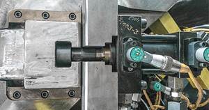
- When checking for this type of tooling wear, a quick and accurate procedure is to interchange new tooling with old, examining the different fits under a microscope. Be sure to orient the tooling as it runs in the mold and pay attention to any track marks on the tooling. This will allow you to feel the movement and see the clearance (wear) between the tooling as you swap back and forth. If you want to measure the movement, this can be done by setting up a dial test indicator on a granite surface plate perpendicular to the movement you want to measure (see photo). Be sure to stone off any burrs, dings, or surface irregularities that prohibit the tooling from sitting flat on the surface plate.
- Angled surfaces should be checked on a sine plate with the dial test indicator for flatness and hobbed areas.
- Once a determination is made as to what tooling will be replaced, grind or etch the mold position number on the new tooling and reinstall. These steps are repeated until all defects are corrected.
About the Author
Steven Johnson is the maintenance systems manager for Progressive Components and has his own business, MoldTrax in Ashland, Ohio. He can be reached at steve@moldtrax.com or (419) 289-0281.
Related Content
Design Your Tools for Moldability ... and Maintenance
In the initial design phase, when considering the structure and elements of the tool, are you designing them to be maintenance friendly? Canon Virginia has used this approach and preventive maintenance to make tool replacement a thing of the past. You can, too. Here’s how.
Read MoreHow to Achieve Simulation Success, Part 2: Material Characterization
Depending on whether or not your chosen material is in the simulation database — and sometimes even if it is — analysts will have some important choices to make and factors to be aware of. Learn them here.
Read MoreThe Impact of Hydraulics on Tool Design -- Part 1 of 2
Get a better understanding of their use, proper sizing, and how the tool design and setup in the machine can impact failures in manufacturing.
Read MoreBack to Basics on Mold Venting (Part 1)
Here’s what you need to know to improve the quality of your parts and to protect your molds.
Read MoreRead Next
For PLASTICS' CEO Seaholm, NPE to Shine Light on Sustainability Successes
With advocacy, communication and sustainability as three main pillars, Seaholm leads a trade association to NPE that ‘is more active today than we have ever been.’
Read MoreLead the Conversation, Change the Conversation
Coverage of single-use plastics can be both misleading and demoralizing. Here are 10 tips for changing the perception of the plastics industry at your company and in your community.
Read MorePeople 4.0 – How to Get Buy-In from Your Staff for Industry 4.0 Systems
Implementing a production monitoring system as the foundation of a ‘smart factory’ is about integrating people with new technology as much as it is about integrating machines and computers. Here are tips from a company that has gone through the process.
Read More


