Understanding Fountain Flow in Injection Molding
The phenomenon of fountain flow affects almost every aspect of the molded product—starting with filling, extending to pack and hold, and ultimately manifesting in part defects like bubbles and voids.
To mold acceptable parts that meet cosmetic and dimensional specifications, it is important to understand the basics of fountain flow and how it exerts itself throughout the entire molding process.
In thermoplastic injection molding, the mold is always said to be “cold”—that is, relative to the temperature of the plastic melt. A mold temperature of 330 F for a PEI material is still “cold” compared with the resin’s 750 F melt temperature (Fig. 1). As the plastic melt touches the cooler mold steel, the plastic will freeze instantaneously and form a skin. The incoming plastic will then move farther ahead of this frozen layer and come in contact with the mold steel in the front, continuing to form a frozen layer. As the melt progresses further, the frozen layer at the start of injection gets thicker and thicker, and the flow channel gets smaller and smaller in its cross section. This “inside-out” flow of the plastic mimics the flow in a water fountain, therefore it is called fountain flow.
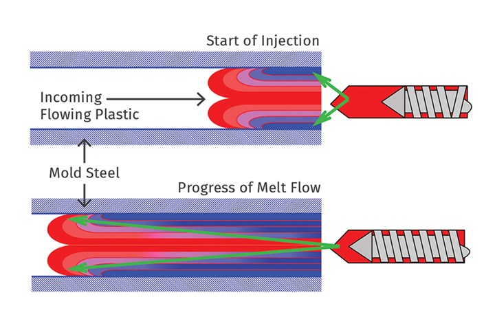
FIG 1 Depiction of fountain flow. (All Illustrations: S. Kulkarni)
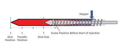
During the fill phase (Fig. 2), the plastic enters the mold at a relatively fast rate and forms the skin. This means that the skin of the part is always formed by the plastic that is in the front of the melt pool in the molding barrel—that is, the plastic closest to the nozzle tip. If you visualize the melt pool divided into 10 sections as shown in Fig. 2, sections 1 to 7 are the ones that will form the skin of the part. In a cold-runner mold, the plastic in the nozzle tip will end up as the skin on the sprue.
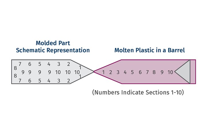
FIG 2 Relationship between the position of the melt in the barrel and the position of the melt in the mold.
The pack-and-hold phase is used to compensate for the shrinkage that will take place after the injection phase. In theory, plastic should be added at the rate of the reduction in volume after the injection phase. This plastic for the pack-and-hold phase comes from sections 8, 9 and 10, which are immediately in front of the screw tip.
Fountain flow has a powerful impact on quality, and accounting for it is essential to becoming a better processor.
The images in Fig. 3 were taken from parts molded during a color change from clear to yellow. The sprue has a clear skin, and the yellow at the back of the melt pool shows up on the inside of the runner and part. The cross-section of the sprue also shows this very clearly. Further, if you look at the part, the section near the gate is being packed out by the yellow plastic. This is the plastic that is last to enter the cavity and is used to compensate for the shrinkage. The images clearly demonstrate fountain flow.
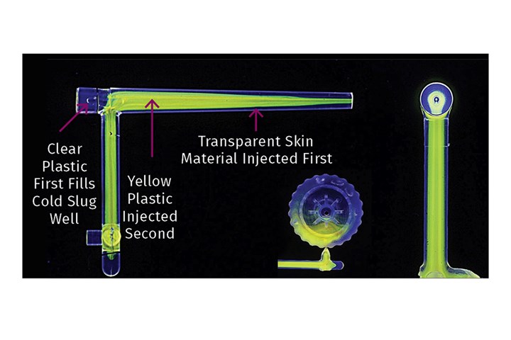
FIG 3 Evidence of fountain flow during color change.
The physics of fountain flow also help us understand several phases of the injection molding process, as well as these defects and other phenomena:
Splay: This is a common defect that shows up as shiny streaks on the part and is caused by the presence of volatiles in the melt (Fig. 4). Volatiles are created from moisture in the plastic, degradation of additives or plastic, and/or air mixed in the melt. The volatiles come between the mold surface and the plastic melt, preventing the melt from picking up the texture of the mold steel and therefore resulting in a shiny or silvery appearance on the part. The volatiles can also get smeared across the mold surface, resulting in streaks.
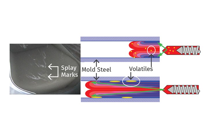
FIG 4 Splay caused by trapped volatiles being smeared in between the mold steel and the plastic melt.
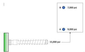
Pressure-Limited Process: As the plastic enters the mold and experiences fountain flow, the frozen layers get thicker and thicker, and the flow channel gets smaller and smaller (Fig. 5). The plastic must now travel through a smaller channel over a longer distance towards the end of fill. To maintain a constant injection velocity of the screw, the required pressure is constantly increasing. If the required pressure reaches the maximum pressure of the machine, the actual screw injection velocity will slow down. This is called a pressure-limited condition and can cause problems with part filling and/or part quality. Injection speeds must be set such that the flow front does not freeze off before it reaches the end of fill.
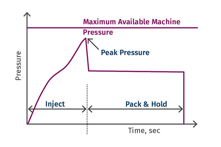
FIG 5 Peak required pressure must be less than max available machine pressure.
Voids: A void is a vacuum space that is usually seen in thick sections of parts molded from tough or hard materials like polycarbonate, acrylic or polystyrene. If sufficient packing pressure is not available to pack out the part, voids will form. As the plastic fills the cavity, the plastic along the walls cools, while the internal melt shrinks from the inside out, causing a void. The void can be considered an internal sink, and additional plastic must be added to pack it out. Visualizing fountain flow, this plastic will come from the melt that is in front of the screw tip.
Bubbles: If there is not enough venting in the mold, as the plastic flows to form the skin, air can get trapped inside the part, forming bubbles. The part cannot be packed out any further because of the presence of air. Venting is the solution to this defect.
Molecular and Fiber Orientation at the Surface: During injection, the molten plastic molecules are always oriented in the direction of flow. As soon as these oriented molecules touch the cold mold, they freeze in this oriented state. The molecules on the inside are not yet solidified during the pack-and-hold phases, and therefore begin to relax. This relaxation causes the loss of orientation. Therefore, with thick parts, there is an oriented outer layer and an unoriented inner layer. This is also true with glass- and other fiber-filled materials, where the glass or other fibers are oriented on the skin of the part.
There are many applications of fountain flow in injection molding. While it represents a simple concept, it has a powerful impact on quality, and accounting for it is essential to becoming a better processor.
ABOUT THE AUTHOR: Suhas Kulkarni is the founder and president of Fimmtech, San Diego, an injection molding service-oriented firm focusing on Scientific Molding. Fimmtech has developed several custom tools that help molders develop robust processes, and its seminars have trained hundreds of individuals. Kulkarni is an author of the best-selling book, Robust Process Development and Scientific Molding, published by Hanser Publications. Contact: (760) 525–9053; suhas@fimmtech.com; fimmtech.com.
Related Content
What to Look for in High-Speed Automation for Pipette Production
Automation is a must-have for molders of pipettes. Make sure your supplier provides assurances of throughput and output, manpower utilization, floor space consumption and payback period.
Read MoreKnow Your Options in Injection Machine Nozzles
Improvements in nozzle design in recent years overcome some of the limitations of previous filter, mixing, and shut-off nozzles.
Read MoreHow to Reduce Sinks in Injection Molding
Modifications to the common core pin can be a simple solution, but don’t expect all resins to behave the same. Gas assist is also worth a try.
Read MoreUnderstanding the Effect of Pressure Losses on Injection Molded Parts
The compressibility of plastics as a class of materials means the pressure punched into the machine control and the pressure the melt experiences at the end of fill within the mold will be very different. What does this difference mean for process consistency and part quality?
Read MoreRead Next
Consider the Cushion When Seeking Shot-to-Shot Consistency
Creating and maintaining a consistent cushion is a key step in achieving shot-to-shot consistency. Learn what cushion is and how it affects part quality.
Read MoreResidence Time and Residence-Time Distribution—Part 1 of 2
Failing to calculate and accurately account for residence time can compromise material integrity before it’s even injected.
Read MoreA Systematic Approach to Process Development
The path to a no-baby-sitting injection molding process is paved with data and can be found by following certain steps.
Read More

