What You Need to Know About Blade Ejectors: Part 3
Follow these guidelines to prevent premature wear, flash and galling. The focus here is on corner radii.
When machining a slot or hole by milling, grinding or EDM, you will always have a very small inside corner radius. Most standard ejector blades have dead-sharp corners. If this is not taken into consideration, the ejector blade will most likely gall and seize within the first few minutes of sampling a new mold. Therefore, a small radius must be added to some or all four corners of the ejector blade, depending on how it was installed. Unless the slot or hole is relieved, the length of the radius on the ejector blade must be slightly longer than the stroke of the ejector plate, plus the length of the bearing surface.
Some moldmakers prefer to chamfer the corners instead of adding a radius. I don’t recommend doing this because it usually results in slight down-flash in the corners when molding medium- to low-viscosity resins at high injection pressures. However, chamfering the edges is a relatively simple method for relieving the corners—starting about ¼ to ½ in. from its front face. An alternate relief method is to machine the hole or slot in the mold on a slight taper—½° per side or less—after the first ¼ to ½ in.
Stoning, grinding, hard milling, or EDMing radii on an ejector blade is time-consuming and therefore expensive, especially when you only have to modify a few pieces. Any work done by hand will require the blade to be numbered and keyed, so that it can be put back in its original position and orientation when the mold undergoes preventive maintenance or repairs.
I examined the websites of 33 companies that sell ejector pins. Of those, only nine offer ejector blades as a standard component. Five of these suppliers were domestic and four were offshore. Of those five domestic suppliers, only one offers blades with corner radii as a standard. It’s an option for a few more, but with a longer lead time. They are available with 0.005-, 0.006-, 0.007-, 0.008-, 0.010- and 0.012-in. radii, having a tolerance of ±0.0010 in. A radius can be added to any or all four corners as dictated by the method of installation.
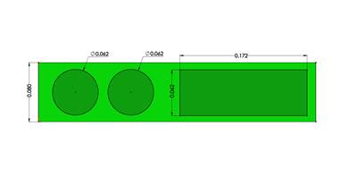
EDM wire ranges from 0.007 to 0.016 in. diam., but 0.008, 0.010 and 0.012 in. are the most commonly used sizes. When you consider the required over-burn during the EDM process, the smallest radius you can cut with the commonly used wire diameters is between 0.0050 and 0.0080 in. This explains why one German supplier of ejector blades only offers blades with 0.0080-in. corner radii—on all four corners, or on two corners of one of the wide sides.
A well-respected mold designer and friend of mine told me that he prefers to wire-EDM the holes for blade ejectors. He says that instead of taking the time to add radii to the ejector blade, he scallops or “bumps out” the corners of the hole, as shown in Fig. 1A. He has done this dozens of times and never had a flashing issue. The skeptic that I am, I ran the numbers to verify this idea. I made a 0.008-in. radius coincident with the sharp corner of the blade.
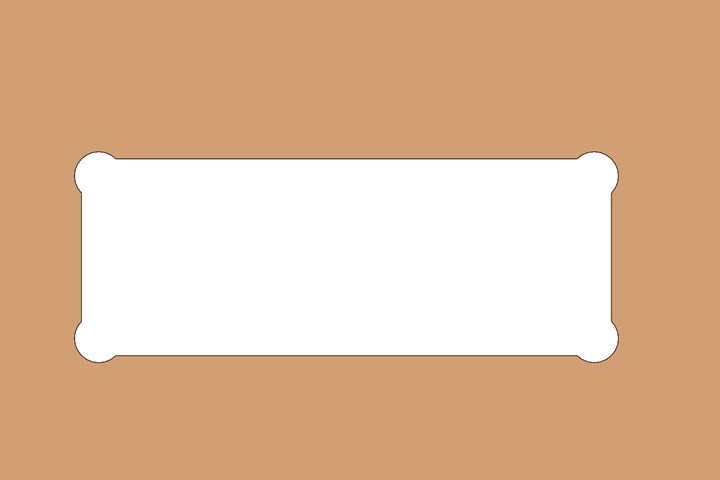
FIG 1A Wire EDMed ejector-blade hole with bumped-out corners.
Despite this best-case scenario, it left a 0.0023-in. gap on the sides, as seen in Fig. 1B, which is well above the recommended vent depth for most materials. The numbers don’t add up to support my friend’s design, and yet I trust him when he says it works, so I have to assume that when material flows into a long, narrow crevice, like a deep rib, the amount of pressure drop must be so great that there is not enough pressure to force any material down the sides of the bumped-out corners.
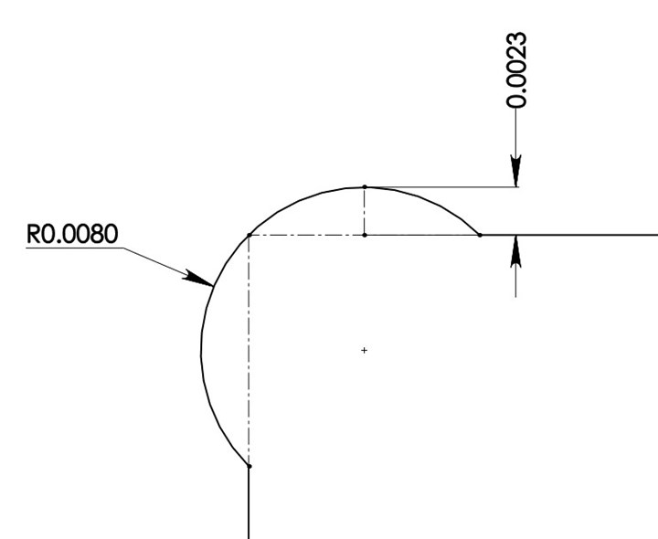
FIG 1B Gap dimensions on bumped-out corners.
But I also suspect that if this method were used near a gate, where the injection pressure is much higher, it would, in fact, flash down the corners. However, with a very small-diameter wire, a minimized amount of over-burn, and a secondary trim pass, those gaps can be as small as 0.0010 in. I mention this design trick so you have another option at your disposal. Just use caution and forethought if you do.
Another trick you can try is to use conventional—also known as ram or sinker—EDM to touch up the corner radii left in the wire-EDMed hole. With the right graphite and proper machine settings, the corner radius can easily be 0.0010 or less.
One Japanese mold-component supplier offers ejector blades with a full radius on the narrow ends, as shown in Fig. 2. I really like this idea when the blade is installed in a wire-EDMed hole. Instead of having four faces with surface contact, you have two with surface contact and two with line contact. This also eliminates the need to account for the four small radiused corners of the hole.
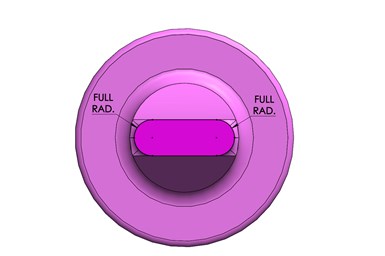
FIG 2 Ejector blade with full-round ends.
Venting
Blade ejectors are often used at the base of a deep rib, which is one of the last places to fill. Venting in this location is almost always essential to prevent dieseling and erosion of the core. Add vents to an ejector blade similarly to how you would add them to a parting line. Grind a small vent to a depth appropriate for the type of resin with a 0.030- to 0.080-in. land length. Then add a deeper relief channel down the length of the blade that leads out to the atmosphere. It is best to add vents only on the wide side(s) and never on the full width of the blade in order to maintain some bearing surface, as shown in Fig. 3. In addition to the benefit of exhausting the gas from the cavity, vents also reduce the amount of surface contact area, which increases the longevity of both the blade and the mold.
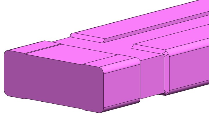
FIG 3 A vented ejector blade.
Vent ejector blades at the bottom of a deep rib.
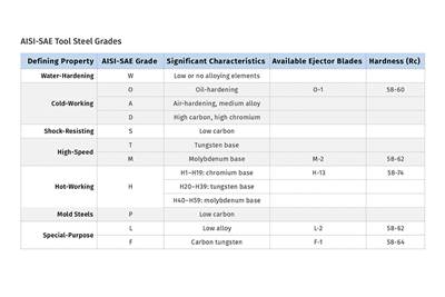
One of the smartest toolmakers I know shared with me his manufacturing method for ejector blades. He takes a block of O-6 steel and wire-EDMs a blade, as shown in Fig. 4. The corner radii are 0.001 in. larger than the corner radii in the wire-EDMed hole in the core. This reduces the chance of contact and galling in these critical locations. The blade has 0.0015 in. of extra stock on all four sides, which is later ground off and polished. This eliminates the EDMed surface from rubbing against the other EDMed surface. The wire path also includes the required vent, which saves some secondary machining.
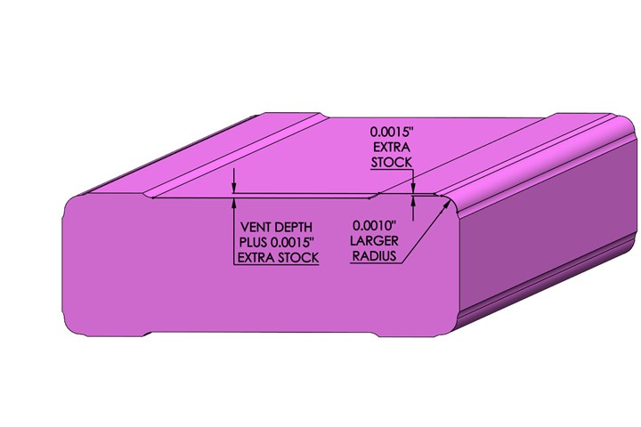
FIG 4 A wire-EDMed ejector blade.
Unsupported Length
Since ejector blades are typically very thin, they are prone to buckling under pressure while trying to eject a part. There are mathematical formulas for calculating whether a blade might buckle, but one of the primary variables is how much force is required to eject the part. That value is, at best, an estimated guess, because it is dependent on so many factors, such as the amount of pack and hold pressure. Therefore, it is crucial to keep the unsupported length to a minimum. The unsupported length is the distance between two locations where the blade is held or supported.
A split bushing, as shown in Fig. 5, can often help minimize the unsupported length for various mold designs, as well as being a simple component to repair in the event of wear, erosion, or galling. Ideally, this split bushing can be flush with the parting line or flush with the bottom of a deep rib. If you can design the mold in this fashion, off-the-shelf ejector blades can be used with somewhat less concern about steel types and hardnesses causing adhesive wear and galling.

FIG 5 A blade ejector retained in a split bushing.
If the ejector blade is thin and the unsupported length is large, some method of supporting the blade is required to prevent buckling. I know of only one such off-the-shelf method, from a German mold-component supplier, but it takes up a lot of room in the ejector plate and won’t allow for multiple blades to be in close proximity to one another. While there must be a variety of ways to support a very long or thin blade, the one I am going to describe is the most appealing.
Start by wire-EDMing a piece of ground stock to create just the blade portion with the desired length, width and depth, as shown in Fig. 6. These are referred to as rectangular-shank ejector blades. They are also available as a standard component from some of the offshore suppliers in thicknesses as small as 0.018 in.
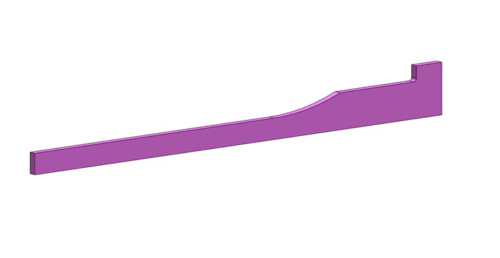
FIG 6 A wire-EDMed rectangular-shank ejector blade.
Grind a slot the thickness of the blade into a core pin, as shown in Fig. 7. A copper-alloy core pin with 30 to 40 Rockwell C hardness works well in this application due to its natural lubricity. An alternate method is to wire-EDM the slot all the way through the core pin.
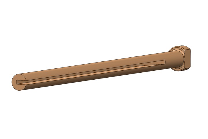
FIG 7 A keyed and slotted core pin to support an ejector blade.
Install the ejector blade and slotted core pin into the mold as shown in Fig. 8. Don’t forget the recess in the B-retainer plate for the shoulder of the blade.

FIG 8 Cross-section of a well-supported thin ejector blade.
Lubrication Reduces Friction
Friction, and the heat generated from friction, is one of the primary causes of galling. Proper lubrication is extremely beneficial in reducing friction and the chances of galling. Unfortunately, you can’t load up ejector blades with grease because it will often migrate or “bleed-out” onto the surface of the molded parts. Ejector blades are notorious for this. But you can grind or hard mill very shallow grease grooves in the side of the blade, the same as you would a wear plate for a cam.
Ejector blades must be well lubricated.
There are dozens of commercially available lubricants specifically formulated for sliding mold components. Some say they do not melt; some contain fluoropolymer; some contain lithium or molybdenum disulfide, some are applied “dry”; and some are specifically designed for the food and medical industries. It is important to note that you don’t want to mix different types of grease. They may not be compatible with one another. If you are going to switch the type of grease you are using, make sure the original type is completely removed. If you have a problem with bleed-out or lack of lubricity, review your production practices before switching to a different type of lubricant.
One of the biggest culprits of poor performance is using mold cleaner to clean the parting line of the mold and then forgetting to re-apply lubricant to the ejector pins, sleeves and blades. When performing preventive maintenance, don’t forget to clean the bore holes with solvent-soaked pipe cleaners. Better yet, use an ultrasonic cleaning tank, because lubricants cannot get into the tiny imperfections of the steel if they are covered in debris, outgassed deposits, or dried lubricants.
Designing an injection mold to work well and last a long time with minimal repair costs and down-time is not difficult if you pay attention to the details.
ABOUT THE AUTHOR: Jim Fattori is a third-generation molder with more than 40 years of experience in engineering and project management for custom and captive molders. He is the founder of Injection Mold Consulting LLC in Pennsylvania. Contact: jim@injectionmoldconsulting.com;
injectionmoldconsulting.com
Related Content
What You Need to Know About Leader Pins and Bushings
There’s a lot more to these humble but essential mold components than you might suspect. Following the author’s tips could save much time, money and frustration.
Read MoreHot Runners: How to Maintain Heaters, Thermocouples, and Controls
I conclude this three-part examination of real-world problems and solutions involving hot runners by focusing on heaters, thermocouples, and controls. Part 3 of 3.
Read MoreBack to Basics on Mold Venting (Part 1)
Here’s what you need to know to improve the quality of your parts and to protect your molds.
Read MoreHow to Design Three-Plate Molds, Part 1
There are many things to consider, and paying attention to the details can help avoid machine downtime and higher maintenance costs, and keep the customer happy.
Read MoreRead Next
What You Need to Know About Blade Ejectors: Part 2
Follow these guidelines to prevent premature wear, flash and galling.
Read MoreWhat You Need to Know About Blade Ejectors: Part 1
Follow these guidelines to prevent premature wear, flash and galling.
Read MoreThree Key Decisions for an Optimal Ejection System
When determining the best ejection option for a tool, molders must consider the ejector’s surface area, location and style.
Read More


