Tooling: How to Properly Size Gates, Runners and Sprues, Part 4
How to get the sprue, runner and gate sizes close to ideal the first time around.
In part one of this series (in March) I discussed the importance of proper gate depths and gate widths. In part 2 (April) I covered two different types of gates, as well as gate land length and gate-freeze time. In part 3 (May) I discussed edge gates and runner sizes. This month I will discuss runner surface finish; dispelling some bad advice; and how to size the sprue bushing.
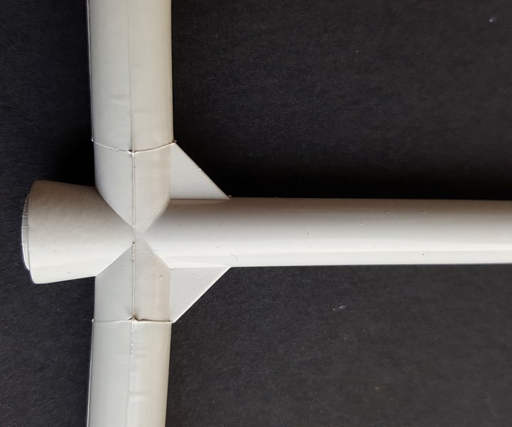
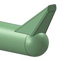
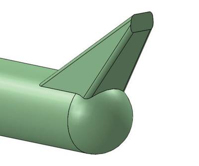
Having a large mass at the parting line is undesirable, but reducing the sprue’s orifice size is worse. Better choices include reducing the length or internal taper of the sprue bushing, using a bushing made of a copper alloy, increasing cooling around the bushing, adding gussets adjoining the sprue to the primary runner (shown here), or replacing the cold sprue with a hot bushing.
Several industry experts say the runner channels should be polished to the same surface finish as the cavity, or between 5 and 50 micro-inches (RMS). This reportedly is necessary to minimize the pressure drop and help with release from the mold. Even if this theory were true, I would suspect it would be almost immeasurable and most likely inconsequential.
Another industry expert doesn’t believe a runner needs to be polished at all, unless it is required for ejection purposes. He says the surface finish doesn’t matter because plastic exhibits fountain flow. As molten plastic flows down a runner channel, it sticks and solidifies to the cold surfaces of the mold. Once it sticks, it has zero velocity. The center of the melt continues to flow—like a fountain—continually depositing additional material from the hot center to the cold outer walls.
I have an alternate perspective on whether or not you should polish the runner channels. There is a direct correlation between surface finish and surface area. If a runner channel has deep cutter marks, it has an increased surface area, as compared to one that was polished. Having a rough surface finish in the thicker runner sections could be helpful in reducing the solidification time. Conversely, having a smooth surface finish on the thinner runner branch feeding the gate could be helpful to ensure the flow channel doesn’t solidify too quickly, which can affect the ability to pack out the cavities. The only negative aspect I can think of related to not polishing a runner system is that a runner system full of cutter marks is not going to appear to be finished by the customer.
Whatever your belief, you must draw polish the sprue bushing and any type of subgate, to assist in their release. This polishing requirement does not apply to all materials. Polyolefins and most elastomers perform better with a light vapor-honed finish—after you remove any cutter marks. The stipple finish reduces the surface tension for easier release.
Draw polish the sprue bushing and any type of subgate.
Determine the Sprue ‘O’ Dimension
In researching this article, I found very little information on how to determine the best orifice size for a sprue bushing. That seemed very strange to me, because the size of the sprue orifice is extremely important. It is, in effect, the gate that feeds the mold’s internal melt-delivery system. And just like an actual gate, you don’t want it to be too large or too small.
In several textbooks and material-supplier design guides, I read things like “The diameter at the outlet of the orifice should be roughly 1-mm greater than the diameter of the connecting runner”; and “The outlet sprue diameter should be at least 1.5-mm larger than the wall thickness of the part being molded.” I thought to myself—these are two of the dumbest things I’ve ever read. Never size a sprue based on how small or how big it will be where it meets the primary runner, or what the wall thickness of the part is.
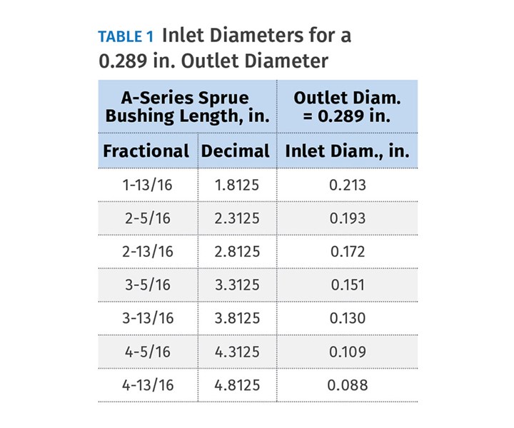
Let’s assume you had a 0.250-in. primary runner diameter. Using that first recommendation, the outlet diameter of the sprue bushing should be 0.250 in. + 0.039 in. (1.0 mm) = 0.289 in. Table 1 shows what the resulting orifice, or inlet diameter would be for the seven commercially available A-Series sprue-bushing lengths, which have the standard ½ in./ft, or 2.37° included internal taper. You can see that even the shortest sprue bushing is going to have a restrictive inlet for a ¼-in. diam. runner.
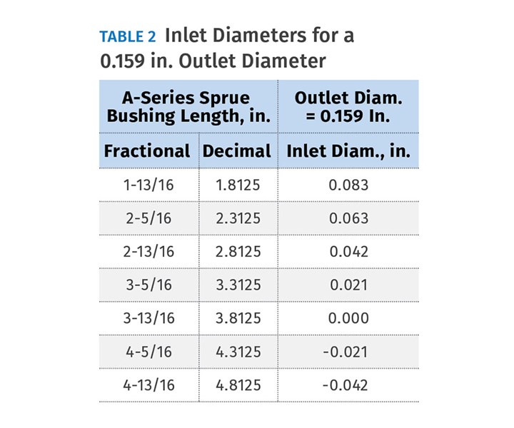
The second recommendation is even worse. Let’s say the part has a uniform 0.100-in. wall thickness. Using this logic, the outlet diameter of the sprue bushing should be 0.159 in. Table 2 again shows what the resulting orifice or inlet diameter would be for the seven commercially available A-Series sprue-bushing lengths, with the same standard internal taper. Not only is the short sprue bushing extremely restrictive, the longer sprue bushings are actually negative numbers!
It is my experience that more often than not, the sprue orifice is undersized.
It is my experience that more often than not, the sprue orifice is undersized. Many designers just don’t know how to determine the proper sprue diameter. In fact, in a few cases, the undersized sprue froze off before the runner or the gate to the part did. That’s why when you do a gate-seal or gate-freeze study, you need to chart the weight vs. the hold time for both the parts and the runner separately. The weight of the runner must continue to increase after the weight of the parts stop increasing. If it doesn’t, it means either the sprue or one of the runner branches is undersized and it froze off before the gate to the part did. You’ll never be able to control your process if that happens.
There is another problem with having an undersized sprue-bushing orifice that is rarely, if ever considered. If I told you that the amount of shear imparted to the material as it goes through a sprue bushing can be greater than the amount of shear as it goes through a gate, you would probably say, “How can that be possible when a gate is so small and a sprue-bushing orifice is so large?” In order to prove it to you, you need to know two formulas for calculating the apparent shear rate. The first formula is for round shapes, such as a sprue orifice or a conical subgate. The apparent shear rate is equal to 32Q ÷ (π × D3), where Q is the flow rate of the polymer and D is the diameter of the round orifice.
There can be more shear in the sprue bushing than the gate.
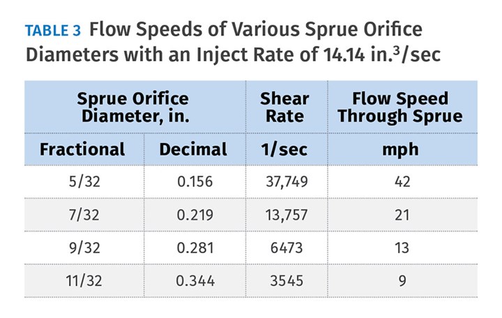
Using this formula, let’s look at the shear rate and the flow speed of material going through different sprue-bushing orifice diameters. If you have a machine with a 3-in. diam. barrel and an injection velocity of 2 in./sec, the flow rate, or Q, coming out of the machine nozzle tip will be 14.14 in.3/sec. Table 3 lists the shear rates and flow speeds for the four commercially available sprue-bushing orifice diameters for this 14.14 injection flow rate. Obviously, the smaller the orifice diameter, the faster the material is going to flow through it. The faster the material flows, the higher the shear rate. Note: Flow Speed (mph) = Flow Rate (in.3/sec) ÷ Flow Area (in.2) × 0.0568.
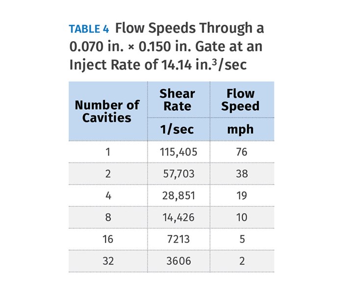
The second shear-rate formula is for rectangular shapes, such as an edge gate. The apparent shear rate is equal to 6Q ÷ (W×H2), where Q is again the flow rate of the polymer, W is the gate width and H is the gate height. For the sake of example, let’s assume the gate to a part is 0.070 in. deep × 0.150 in. wide.
Table 4 specifies the shear rate and the flow speed through each gate for molds with various cavitation—again using the injection rate of 14.14 in.3/sec. As the number of cavities increases, the shear rate and flow speed decrease accordingly. When you compare Table 3 to Table 4, you can see that you may or may not have a problem, depending on the sprue-bushing orifice size and number of cavities. In this example, if you had a 7/32 in. sprue orifice it would have more shear than the gates in a 16- or 32-cavity mold for the given edge-gate size.
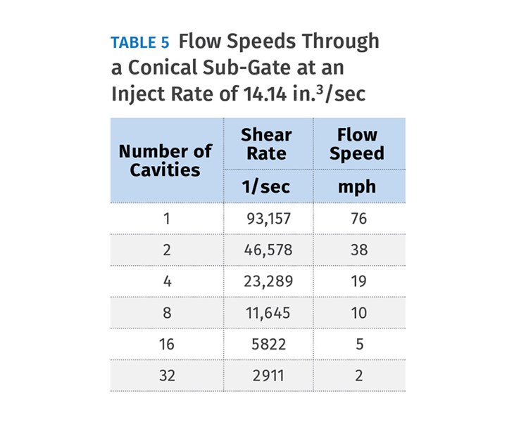
Since I’m the kind of guy that just can’t leave well enough alone, I decided to check something out. I took the 0.070-in. deep × 0.150-in.wide edge gate in the previous example and calculated what the diameter would be for a conical subgate having the exact same flow area (0.070 in. × 0.150 in. = 0.0105 in.2). The math works out to a 0.124-in. diam. gate. I then used the shear-rate formula for round flow areas. The results are shown in Table 5, and they are what you might have expected. The round subgate had slightly less shear than the rectangular edge gate. That’s because a round gate has a lower ratio of flow area to perimeter length than a rectangular gate does. While edge gates are my preference, keep in mind that they will have slightly higher shear than a subgate with an equivalent flow area.
Getting back to how to determine the orifice size of a sprue bushing, use the same formula as we did when estimating the runner diameters in Part 3 of this series. For example, if the diameter of the primary runner was 0.250 in., the sprue-bushing orifice would be: DFEED = 0.250 × 21/3 = 0.315 in. This works out to 58% more flow area than in the primary runner, which makes sense. If the calculated sprue-bushing orifice diameter is not a standard size, modify a standard bushing using a reamer or wire EDM. This also affords you the opportunity to change the included angle if desired.
Now let’s look at the reality of the situation. A ¼-in. diam. primary runner is fairly common, and the formula above for determining the sprue’s orifice diameter is fairly accurate. Table 6 shows the resulting outlet diameters for the seven standard lengths of A-Series sprue bushings. Even the shorter lengths will form a thick mass of plastic at the parting line—considerably wider than the primary runner. The designer will assume this is a bad situation and reduce the orifice size of the sprue.
While having a large mass at the parting line is in fact an undesirable condition, reducing the sprue’s orifice size is worse. The better decision would be to try to reduce the length of the sprue bushing, use a bushing made out of a copper alloy, increase the cooling around the bushing, reduce the bushing’s internal taper, add gussets adjoining the sprue to the primary runner, or replace the cold sprue with a hot bushing.
ABOUT THE AUTHOR: Jim Fattori is a third-generation molder with more than 40 years of experience in engineering and project management for custom and captive molders. He is the founder of Injection Mold Consulting LLC in Pennsylvania. Contact: jim@injectionmoldconsulting.com;
injectionmoldconsulting.com
Related Content
Hot Runners: Truths. Myths, Overlooked Areas: Part 2
Here’s a view from the trenches of a tooling manager who, over 30 years, has experienced the joys and pains of using virtually every type of hot runner on the market. Part 2.
Read MoreWhy Shoulder Bolts Are Too Important to Ignore (Part 2)
Follow these tips and tricks for a better design.
Read MoreWhy Shoulder Bolts Are Too Important to Ignore (Part 1)
These humble but essential fasteners used in injection molds are known by various names and used for a number of purposes.
Read MoreBack to Basics on Mold Venting (Part 1)
Here’s what you need to know to improve the quality of your parts and to protect your molds.
Read MoreRead Next
Part 1: How to Properly Size Gates, Runners and Sprues
Get the sprue, runner and gate sizes close to ideal the first time around—without spending a lot of time on extremely complicated formulas.
Read MoreTooling: How to Properly Size, Gates, Runners and Sprues, Part 2
Get the sprue, runner and gate sizes close to ideal the first time around.
Read MoreTooling: How to Properly Size, Gates, Runners and Sprues, Part 3
Get the sprue, runner and gate sizes close to ideal the first time around.
Read More

