Barrier Screws: Not All Are Created Equal
Let’s take a deep dive into parallel and crossing types and see where each fit in.
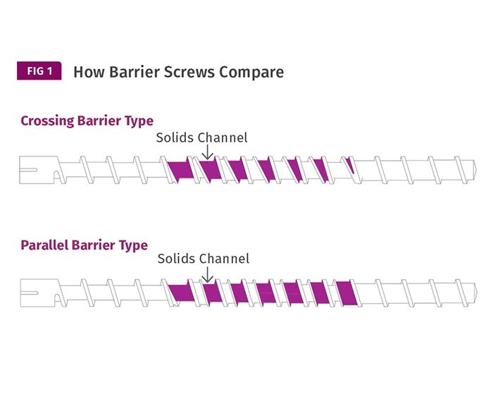
There have been many barrier screws designed over the years to improve plastication. But while they have some common design features, they don’t work exactly the same. I have found that parallel barriers (see Fig. 1) have some advantages over crossing barriers.
First—and importantly for me as a designer— it’s much easier to calculate the melting and pumping performance of parallel barriers, which cuts down on design time. Although that’s not of general benefit, the crossing barriers require many more calculations to accurately calculate the melting rate and output. This is because the depths and widths of both the solids and melt channels are changing continuously as they advance down the screw. This leads to potential design errors. Simply determining the channel volumes is a math exercise.
From a performance viewpoint, a crossing barrier design requires more length to achieve the same surface area at the barrel wall. In screws of lesser L/D, this can necessitate designing for lower outputs or take a chance on poorer melt quality. I’ve evaluated a number of crossing barrier and parallel barrier designs and found the crossing barriers typically had about two-thirds the area in the solids channel compared with those having a parallel barrier, if they had equal-length barrier sections and flight leads. The parallel barrier designs I studied all had approximately 66% solids-channel and 33% melt-channel widths. Since barrier designs are intended to improve melt uniformity at higher outputs, the ones having the greater melting area, as determined by the greatest solids-channel area, would be expected to have a distinct advantage.
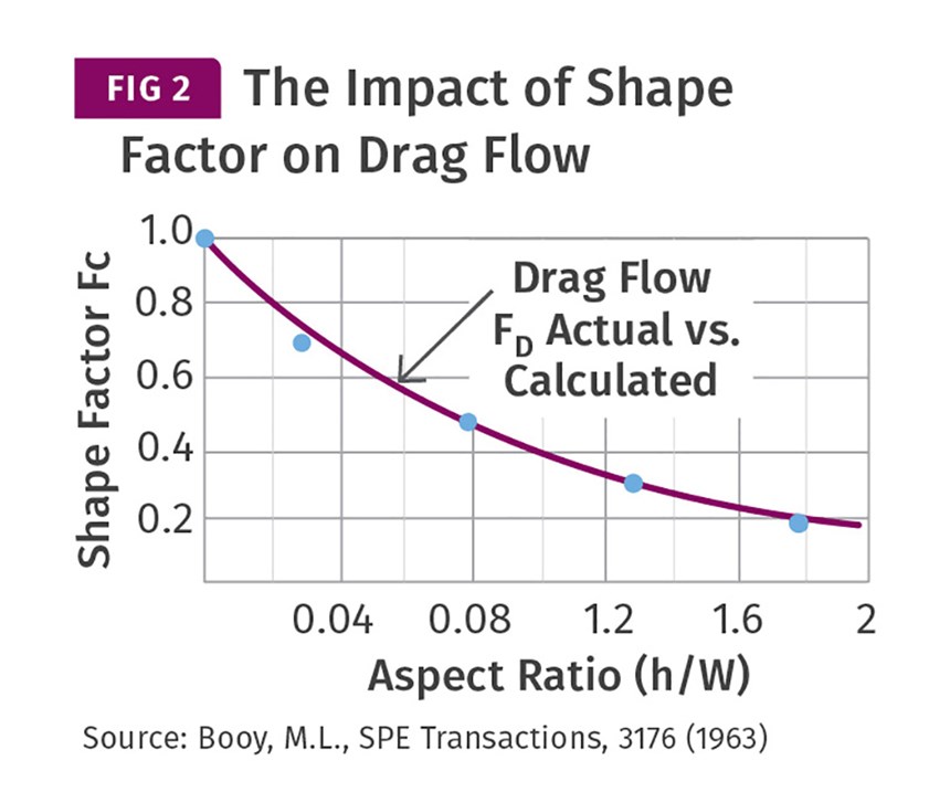
As a second consideration, when the ratio of the depth to width (h/W) of a screw channel increases, there is a reduction in its drag flow. This channel depth/width ratio is commonly referred to as the shape factor. The shape factor affects both the drag flow and the pressure flow. Figure 2 shows the magnitude of the effects of the shape factor for drag flow. For example, when the h/W reaches 0.2, which would correspond to a 3-in.-wide channel with a 0.600-in. depth, the Fc (or factor for drag flow) has reduced to 90% of a calculated drag flow. With a crossing barrier, this indicates decreasing drag flow along the entire solids channel, with a decrease at the middle to about 72% for a channel starting at 3 in. and a constant depth of 0.600 in., with further decreases to its end.
Since drag flow is reducing due to the shape factor as the crossing barrier moves down the screw, there is ultimately a portion of the solids channel—where it becomes very narrow—that does not remove the melt effectively, thereby blocking the introduction of unmelt to that area. This reduced drag flow occurs over roughly the final one-third of the barrier length, further affecting the melting area.
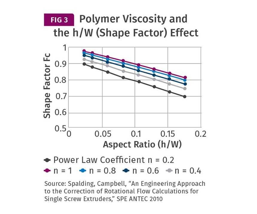
The magnitude of the h/W effect also depends on the polymer viscosity; polymers with a low power law coefficient (i.e., greater shear-thinning tendency) are more affected. A 2010 SPE ANTEC paper by Mark Spalding of the Dow Chemical Company and Greg Campbell of Castle Research Associates, “An Engineering Approach to the Correction of Rotational Flow Calculations for Single Screw Extruders,” shows the effect of the shape factor for polymers with various power-law coefficients (Fig. 3). Spalding’s and Campbell’s research indicates that crossing barrier types would be better suited to polymers with higher power law coefficients.
This means that polymers such as polycarbonate or nylon 66 would be good candidates for crossing barrier designs. Interestingly, PVC screws would be most affected by the Fc. Yet most PVC barrier screws are of the crossing barrier type. But on closer examination, that makes sense because amorphous polymers are not as affected by melting area, since they essentially soften with increasing temperature and never experience a defined melting point.
This is not to say that maximizing the solids area is the only criterion for a superior barrier-screw design, but it’s certainly one of the critical elements. Another consideration for choosing parallel barrier designs is possible distortion of the solid bed during melting. This commonly occurs with a crossing barrier due to the constantly changing width (i.e. shape) of the solids channel, which can lead to solid-bed breakup and poorer melting rate and melt quality. This would indicate that parallel barriers would be more appropriate for crystalline polymers that have a fixed melting point, while not so important for amorphous polymers.
Crossing barriers also generally require a deeper solids channel in order to achieve output equal to that of a parallel barrier because of the previously mentioned pumping limitation. The required deeper channels reduce heat transfer both from the barrel and from the melt to the unmelt. Each of these limitations can be overcome if there is sufficient screw length, as there are many successful crossing barrier screws in service, but the different requirements of crystalline and amorphous polymers must be considered in the design and not simply substituted geometrically one for the other.
ABOUT THE AUTHOR: Jim Frankland is a mechanical engineer who has been involved in all types of extrusion processing for more than 40 years. He is now president of Frankland Plastics Consulting, LLC. Contact jim.frankland@comcast.net or (724) 651-9196.
Related Content
Why Are There No 'Universal' Screws for All Polymers?
There’s a simple answer: Because all plastics are not the same.
Read MoreHow Screw Design Can Boost Output of Single-Screw Extruders
Optimizing screw design for a lower discharge temperature has been shown to significantly increase output rate.
Read MoreIs a Gear Pump Right for Your Single-Screw Operation
As with everything else, there are pros and cons, but more of the former. They provide processors higher rates while decreasing the temperature of the extrudate while enabling downgauging.
Read MoreMaximize the Cooling Capacity of Your Extrusion Line
Maximizing output in extrusion requires a thorough understanding of not only the cooling requirements of the extruder but of the extrudate as well.
Read MoreRead Next
Lead the Conversation, Change the Conversation
Coverage of single-use plastics can be both misleading and demoralizing. Here are 10 tips for changing the perception of the plastics industry at your company and in your community.
Read MoreBeyond Prototypes: 8 Ways the Plastics Industry Is Using 3D Printing
Plastics processors are finding applications for 3D printing around the plant and across the supply chain. Here are 8 examples to look for at NPE2024.
Read More
.jpg;width=70;height=70;mode=crop)


