A Processor's Most Important Job, Part 9: Avoid Molded-In Stress
How to establish molding conditions that minimize internal stress in a part.
This is part nine of an eleven-part series focused on the most important job of a processor. To read the rest of this series, click these links:
part one, part two, part three, part four, part five, part six, part seven, part eight, part ten, part eleven.
In the previous column, we discussed the fundamental connection between variations in the condition of the polymer at different locations in a molded part and the level of internal stress in that part. These variations are influenced to a significant extent by processing conditions. Differences in pressure within the mold cavity will produce variations in the way the material shrinks. This is one source of internal stress. The other consideration is differences in the rate at which the polymer cools. Knowledge of these factors allows a processor to establish molding conditions that reduce internal stress in a part. It is not possible to mold a part with zero internal stress.
Even under the best of circumstances, a well-molded part will still have a stress level of 500-600 psi. But poor molding practices can result in stress levels that exceed 3,000 psi. This will result in reduced impact resistance, dimensional instability upon exposure to elevated temperatures and greater sensitivity to failure mechanisms such as environmental stress cracking (ESC). The objective should be to minimize internal stress while still making the part cost-effectively.
Mold Filling & Packing
Mold filling and packing have a significant influence on the pressure distribution in the cavity. The pressure drop in a flowing polymer system is proportional to the viscosity of the material. Viscosity is influenced by two processing conditions: The melt temperature and the shear rate applied to the material. Higher shear rates result in lower viscosities and can frequently achieve this objective as an alternative to raising melt temperatures. This is the reason that the principles of scientific molding dictate that most of the cavity should be filled at a relatively rapid rate during what is typically referred to as the first stage. The switchover to pack, or second stage, should take place when the cavity is almost full by volume. The velocity of the polymer during the second stage is usually much slower than on the first stage, and this will result in a much higher viscosity.
For some polymers, the viscosity on the second stage can be more than 10 times greater than on the first stage. Therefore, switching over too early means that it is more difficult to pressurize the polymer uniformly. Switching over too late will result in an overpressure condition that can cause flash and may even damage the mold.
The relationship between the mold-filling strategy and the pressure distribution across the cavity can be readily demonstrated if the cavity contains pressure transducers at the beginning and end of the flow path. The pressure will never be exactly the same at these two locations, but good mold-filling practices can reduce the difference. The more uniform the pressure in the cavity, the more uniform the shrinkage of the material as the polymer cools.
The cooling rate is the other critical factor. Rapid filling introduces a high level of orientation in the polymer. This orientation is at a maximum in the layer of polymer that is just below the mold surface.
This is also the layer of material that cools most rapidly. While some level of orientation can be beneficial, if it is excessive it will represent a source of internal stress. The level of retained orientation and the difference in cooling rate between the surface of the part and the core can be reduced by operating at a higher mold temperature. This reduces the rate of cooling, allowing the polymer to relax to a greater extent as it develops the structure in the part.
Another secondary benefit to running higher mold temperatures is that it slows down the rate at which the frozen layer develops. The instant that the molten polymer enters the mold, the material at the surface begins to freeze. The flow of the polymer through the cavity is continued by molten material moving through the interior layers that have not yet solidified, a phenomenon known as fountain flow. The shearing forces that develop between the exterior layers that have stopped flowing and the interior layers that are still moving are a source of internal stress. So, to the extent that the rate of frozen-layer development can be reduced, the internal stress can be reduced also. Many cosmetic defects, such as tiger stripes, flow lines and orange peel, are symptoms of a frozen layer that develops too early in the mold-filling process.
In addition, recall that the pressure drop is governed to a significant degree by the size of the flow path. In a round cross-section, a reduction from 0.050" (1.25 mm) to 0.040" in. (1 mm) results in doubling the pressure loss. We tend to think that if a part has a wall thickness of 0.080" (2 mm), this represents the available path through which the polymer flows, regardless of location in the cavity. But in reality, the size of the available flow path becomes smaller as the material moves farther into the cavity, away from the gate or gates. This is another factor in the pressure drop that we observe between the gate and the end of the flow path. Higher mold temperatures reduce the rate of frozen-layer development and allow for achievement of a more even pressure distribution in the cavity.
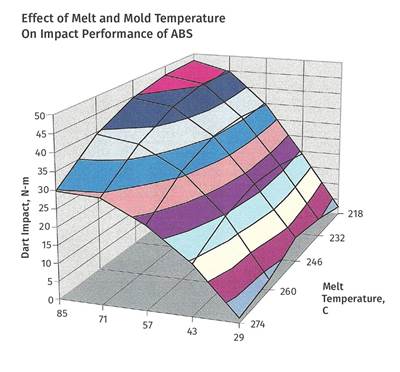
These principles of polymer flow and cooling are behind the observations that were discussed in the previous column. It is interesting that the same attention to mold temperature that ensures optimal crystallization in semi-crystalline polymers also produces optimal properties in amorphous polymers. If mold temperature is thought of as the sole factor in determining cycle time, then there is a great reluctance on the part of the processor to increase it. However, if it is understood that mold temperature and melt temperature work together, then it can be seen that an appropriate balance between the two parameters is the key to optimizing material properties while maintaining a competitive cycle time.
While the focus of these articles has been on processing, it is important to note that the ability to achieve a uniform cooling rate and an optimal pressure distribution in the cavity also depends upon good part design and mold design. Designing a part with large variations in wall thickness, or selecting a gate location that results in filling a thicker section through a thinner section, will create problems that the processor will have difficulty compensating for.
Traditionally, poor design decisions have simply been passed along and it has been left to the processor to figure it out. Frequently the result is a set of process conditions that represent an attempt to correct for the poor design. These often include lower mold temperatures and high packing pressures, the very things that create elevated levels of internal stress. Good concurrent engineering practices call for a thorough discussion between all interested parties during the early stages of product development so that these problems can be solved before the mold is built.
About the Author
Michael Sepe
Michael Sepe is an independent, global materials and processing consultant whose company, Michael P. Sepe LLC, is based in Sedona, Arizona. He has more than 40 years of experience in the plastics industry and assists clients with material selection, designing for manufacturability, process optimization, troubleshooting and failure analysis. Contact: 928-203-0408 • mike@thematerialanalyst.com.
Related Content
What's the Allowable Moisture Content in Nylons? It Depends: Part 2
Operating within guidelines from material suppliers can produce levels of polymer degradation. Get around it with better control over either the temperature of the melt or the barrel residence time.
Read MoreFundamentals of Polyethylene – Part 6: PE Performance
Don’t assume you know everything there is to know about PE because it’s been around so long. Here is yet another example of how the performance of PE is influenced by molecular weight and density.
Read MoreThe Effects of Stress on Polymers
Previously we have discussed the effects of temperature and time on the long-term behavior of polymers. Now let's take a look at stress.
Read MorePart 3: The World of Molding Thermosets
Thermosets were the prevalent material in the early history of plastics, but were soon overtaken by thermoplastics in injection molding applications.
Read MoreRead Next
A Processor’s Most Important Job, Part 10: Fiber-Length Retention
Glass and carbon fibers are often used to increase material strength and modulus. To maintain these properties, the aspect ratio of these fibers must be maintained.
Read MoreA Processor’s Most Important Job, Part 8: Molded-In Stress
How processing adjustments can control molded-in stress.
Read MoreMaking the Circular Economy a Reality
Driven by brand owner demands and new worldwide legislation, the entire supply chain is working toward the shift to circularity, with some evidence the circular economy has already begun.
Read More
.jpg;width=70;height=70;mode=crop)
