MOLDING 2016: New Approaches to Processing, Tooling & QA
The largest-ever annual Molding Conference included newsworthy technical presentations on a variety of injection molding topics. Here’s a selection.
Molding 2016, the 26th annual Molding Conference, drew a record audience of 237 in New Orleans last month. The conference, aimed exclusively at injection molders, was presented by Plastics Technology magazine and its parent, Gardner Business Media. From the 53 technical and business presentations (nine of them by molders), here is a distillation of some of the most newsworthy content. (For more news from the conference, see Starting Up and Keeping Up sections. If you missed Molding 2016, save the date for Molding 2017, April 3-5 in Charlotte, N.C. at the Sheraton Le Meridien hotel.)
MOLDS GET ‘SMART’
Bruce Catoen, chief technology officer for Cincinnati-based Milacron, spoke about the trend toward integrating intelligent devices that “talk” to each other in “smart connected cells” comprising the molding machine, mold, and auxiliaries. Catoen predicted that “smart devices will explode at K 2016,” the mammoth trade show in Dusseldorf, Germany, this October. One of those devices will be Milacron’s new Smart Mold technology, which was announced as an upcoming development at NPE 2015 (see July ’15 show report). This device will be essentially a mold-mounted micro-PC with onboard data storage, connected to sensors in the mold, to the machine controller, and perhaps to the cloud for remote monitoring. It reportedly will provide more data about the mold than has been available up to now—not just than cycle time, “wet” cycle counts, and uptime, but data on abusive treatment of the mold—“like whether it was slammed or overpressured,” Catoen said—in order to predict when preventive maintenance is required. It could also include GPS functionality to enable tracking the mold’s location for “globalized reporting” to companies with international operations.
While saving most details on Smart Mold for the K Show public launch, Catoen revealed that it is now already standard on all new Milacron PET molds and co-injection molds. Catoen also cited results of a test of “smart monitoring” of injection machines using capabilities already available for remote monitoring of machines by molders and Milacron service personnel. In an 18-month test on four presses, Catoen said this “r-monitoring” resulted in 9.8% greater overall equipment efficiency (OEE), more than 50% reduction in downtime for job changes, and 80% of service needs handled remotely rather than sending a technician to the plant, thus saving time and money.
NEW LOW-PRESSURE MOLDING SYSTEM
Rick Fitzpatrick, chief technology officer of Xtrude2Fill (X2F) in Loveland, Colo., presented his new low-pressure molding approach that essentially takes the injection out of injection molding. X2F’s new machine design eliminates the reciprocating screw, high pressures, and difficult-to-manage temperatures of traditional molding for a continuously extruding fixed screw and precise melt and pressure management with any resin.
By eliminating conventional rapid injection and use of friction and shear heating to melt material, X2F’s alternative reportedly requires far less clamp pressure and achieves far more consistent and uniform melt temperature. Instead of the 2-5 tons/in.2 used in standard injection, X2F needs only the equivalent of a pack/hold pressure of 1-1.5 tons/in.2 . That allows for use of aluminum molds and a very small, lightweight press (horizontal or vertical) with a pneumatically actuated toggle clamp and a servo-driven extruder with a shutoff nozzle. X2F’s largest current machine weighs only 800 lb with a 36 x 48 in. footprint and can run on 208V single-phase electricity. That machine can handle mold sizes up to 12 x 12 in. and shot sizes up to a 150 g. The company also makes machines that weigh only 250 lb and run on 110V household power with shot sizes to 30 g.
The patent-pending machine design uses electrical heating to melt material via conductive heating rather than frictional shear heating. Fitzpatrick says his large machine can heat up from room temperature to 450 F in 5-6 min, thanks to barrel walls as thin as 1/8 in. (owing to low-pressure molding) and use of special thermally conductive materials in barrel construction. His process reportedly needs only 10% of the energy consumed in conventional injection molding. Fitzpatrick noted that his smaller press would compare to a 25-ton clamp in a conventional design, but uses only 8.7 tons.
On the controls side, since the process is not rapidly injecting fixed volumes of plastic, the machine can give real-time pressure and volume feedback to confirm part consistency with sensors in the melt. Controlled melt temperature allows molding heat- and shearsensitive materials like biopolymers. And low shear also permits molding highly filled compounds such as metal injection molding (MIM) feedstocks and 50% glass-filled resins. Fitzpatrick says his machine has reprocessed post-consumer reclaim such as metalized snack bags and mixed-resin scrap.
Because of all this, Fitzpatrick believes the X2F process can change the economics of molding. With operating costs as low as $6/hr, molders can afford to use multiple presses and molds with just four and eight cavities, matching the cost/part of 16- and 32-cavity molds in conventional processing.
LASER SINTERING & LIQUID CO2 COOLING
Scott Kraemer, directing manager of corporate design, new technology, and Tech Academy, told the Molding 2016 audience about his latest explorations of laser sintering powdered metal to make tooling parts and making them more productive with liquid CO2 (LCO2) spot cooling. Kraemer’s firm, PTI Engineered Plastics, Macomb, Mich. is a custom molder primarily of medical and automotive parts. A March Close Up article detailed his R&D in “growing” laser-sintered tooling components and incorporating LCO2 cooling.
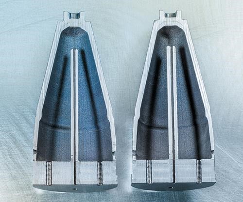
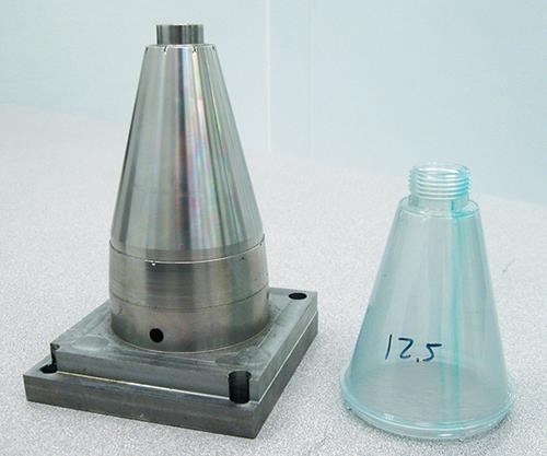
In New Orleans, he presented his latest work, most notably on a 7-in. tall, 3-in. diam. conical mold insert made by laser sintering and finishing with a CNC machine. The part is almost entirely hollow, with a 4 mm wall. Making it hollow eliminated 78% of the metal mass and cut the 3D printing time to 92 hr from the 197 hr it would have taken to make a solid part.
The insert contains a hollow center post to hold a thin capillary tube that distributes LCO2 coolant. When that coolant emerges into the core interior it becomes a “snowstorm” of tiny dry-ice particles. The thin steel wall cools very quickly, reducing the cycle time for the thin polycarbonate part from 46.5 to 41.5 sec. “We could have run faster, except that the runner would stick from incomplete cooling,” Kraemer said. The CO2 gas escapes from the core via two small holes at the base. Unlike water cooling, no return line is required.
Kraemer said this insert was also used for hot/cold molding, where LCO2 cooling dropped its temperature from 160 F to 80 F in 1.5 sec. Kraemer added that LCO2 can be used inside slides and hot-runner sprue bushings. It can even be blown directly onto the outside of core pins at their base, something that can’t be done with water.
MAKING SIMULATION MORE MEANINGFUL
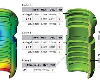
Scott Rogers, technical manager of custom molder Noble Plastics in Grand Coteau, La. (see Apr. ’13 cover story), described a new software approach to predicting dimensions of molded parts. Rogers noted that standard molding simulation with shrink and warp calculations can provide a prediction of molded part geometry with deviations from CAD dimensions shown on a green-yellow-blue color scale. Unfortunately, this type of output does not communicate very well to customers’ quality engineers in the same way as a metrology inspection report on deviations from print. As a result, customers don’t always react to the warning signs in simulation results and make changes in the part or tool design before cutting steel. And when they get the metrology report on the actual molded part, customers are prone to ask, “Why didn’t you predict that would happen?”
To forestall such misunderstandings, Rogers has applied for a patent on a software approach that displays the results of shrink/warp prediction in the form of a standard metrology inspection report from a coordinate measuring machine (CMM) or other instrument. “I can tell the customer, ‘It’s going to be out of flatness by x thousandths, or that hole is going to move by this much.’ It shows the customer what he cares about,” Rogers says.
SOFTWARE AUTOMATES SCIENTIFIC MOLDING
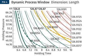
Suhas Kulkarni, founder and president of Fimmtech Inc., San Diego, discussed the latest release (v.8) of the Nautilus software for design of experiments (DOE) and mold qualification. He said Nautilus helps molders validate and troubleshoot their molding process and can result in greater shot-to-shot and machine-to-machine consistency. With his software, DOE is used to determine the cause-and-effect relationships between factors affecting a process and the output of that process, in order to establish a scientific molding process.
Kulkarni believes many molders attempt to adopt scientific molding, or more accurately, portions of scientific molding, but abandon the effort after inconsistent results. That’s where he thinks his Nautilus program can help. “The software gives you all the tools to come up with a robust process that includes the DOE,” Kulkarni said. DOEs are completed within four mouse clicks, allowing molders to analyze the results and get “a simple decision whether the process is robust or not by looking at the data.”
Nautilus was first released in 2007, and a number of features were added in the newest iteration. Among the upgrades, scientific molding studies, DOE studies, troubleshooting guides, and quality data are now all bundled under one project. And once a process is established on one machine, the software gives users the process for any other machine in the molding shop with a click of a button, and the software will establish which machines are and are not capable of molding the part based on established process parameters.
Nautilus can also calculate how the steel dimensions of a mold need to be adjusted so that the parts can hit the nominal dimension. The software has built-in worksheets for the various scientific molding studies, including viscosity curve, cavity balance, pressure drop, cosmetic process window, gate seal and cooling time.
Related Content
Optimizing Pack & Hold Times for Hot-Runner & Valve-Gated Molds
Using scientific procedures will help you put an end to all that time-consuming trial and error. Part 1 of 2.
Read MoreThree Key Decisions for an Optimal Ejection System
When determining the best ejection option for a tool, molders must consider the ejector’s surface area, location and style.
Read MoreInjection Molding: Focus on these Seven Areas to Set a Preventive Maintenance Schedule
Performing fundamental maintenance inspections frequently assures press longevity and process stability. Here’s a checklist to help you stay on top of seven key systems.
Read MoreWhat to Look for in High-Speed Automation for Pipette Production
Automation is a must-have for molders of pipettes. Make sure your supplier provides assurances of throughput and output, manpower utilization, floor space consumption and payback period.
Read MoreRead Next
Introducing 'HD Plastics'
"High Definition Plastics" is a new way of thinking about the benefits of heat/cool molding with induction heating.
Read MoreMedical & Auto Molder Explores New Tech for Tooling & Cooling
Additive manufacturing and liquid-CO2 spot cooling are the firm’s newest tools for boosting productivity and quality.
Read MoreMaking the Circular Economy a Reality
Driven by brand owner demands and new worldwide legislation, the entire supply chain is working toward the shift to circularity, with some evidence the circular economy has already begun.
Read More


