Put Science into Glass-Fiber Compounding on Single Screws
There are still companies that compound glass fibers on single screws. The process is considered an “art,” but can be made more predictable with attention to screw design, speed and length, as well the choice of mixer.
Nowadays, most compounding of short-glass fiber into polymers is done on corotating twin-screw extruders. But many still compound glass fibers on a single screw. Unfortunately, this process is still a bit of an “art.” To avoid breaking the fibers there are numerous restrictions on screw design and operating conditions. Maximization of fiber length has a significant effect on the final physical properties of the compounded polymer, so the value of the final product is largely determined by the amount of fiber breakage.
For a single screw, the blend of the polymer/fiber mix into the extruder feed throat must be closely controlled. The old saying is, “Better mix in, better mix out.” Although there is localized mixing in single screws, there is little axial redistribution, so if the mix entering is not uniform it will exit in much the same way. Uniform distribution of the fibers into the pellet or flake polymer—such as breaking up fiber bundles—is important so that fiber agglomerates do not form early and then cannot be broken up.
Although the screw does not have to be starve fed, its typically better to minimize fill in the hopper and throat so that column pressure does not segregate the mixture due to random solids particle flow. Probably the most critical area for fiber breakage is before any significant melting has formed to fluidize the mass and give the fibers some degree of movement.
The old saying is, “Better mix in, better mix out.”
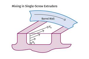
Some fiber breakage is unavoidable; when fiber-filled polymer passes over the screw flights it is subjected to extreme shear rates; the fibers will break unless they are aligned with the shear (see Fig. 1). Most preventable fiber breakage occurs when fibers are forced to make severe bends or sustain high shear forces while locked in a solid polymer/fiber matrix. In the corotating twin screws the fibers are typically introduced at an intermediate downstream location where the polymer is all melted, avoiding this issue.
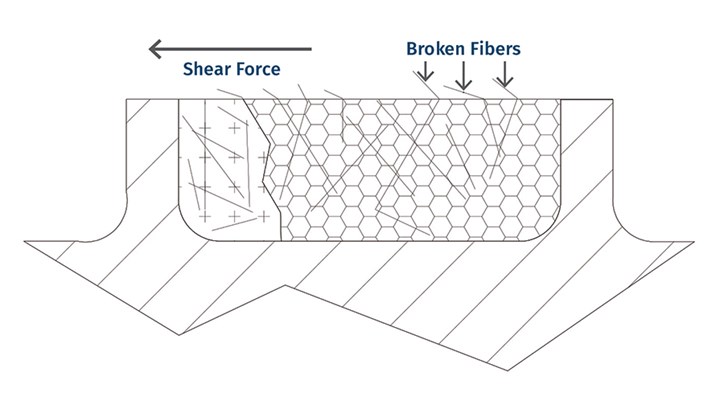
FIG 1 When fiber-filled polymer passes over screw flights, it experiences extreme shear rates;
and unless aligned with the shear, the fibers will break.
In order to reduce fiber breakage, the single-screw design should have a more gradual compression section to minimize plugging of the screw channels with solids. In addition, the compression ratio from the feed to metering should be kept on the low side for any specific polymer to prevent such plugging. Feed sections are also typically several flights longer to develop some melting before compression starts. Higher barrel temperatures in the rear zones can also help to initiate melting as quickly as possible.
Screw speed is also a factor with any particular screw design. Screw speed multiplies the shear forces on the fibers so that output may have to be substantially reduced to minimize the forces applied to the fibers. Head pressure should be kept as low as possible; it’s possible that redesign of the die head will be necessary, as increased pressure causes backflow in the screw, thereby subjecting the fibers to redundant shearing. Greater L/D can be used as an advantage or a disadvantage. Greater L/D will assist in obtaining a complete melt without high-shear mixers or barrier flights, but also subjects the polymer to more repetitive shearing.
For those running glass- or other fiber-filled compounds on a daily basis, determination of the best L/D can be critical. Selecting the ideal L/D can be done by stopping the screw, pushing it out filled, and having the glass length at various L/Ds measured after burning off the polymer.
Crystalline polymers require even more care in order to prevent fiber breakage than amorphous polymers, because they do not soften until reaching their melting point. This makes channel plugging more difficult to eliminate. That should be considered along with the compression rate and feed length. Screw designs that do well processing amorphous polymers with glass fiber are often ineffective with crystalline polymers.
Mixer Choice is Crucial
Mixers require special consideration as well. High-shear mixers like the traditional Maddock design can be used, but they need to be placed well down the screw where there is an expectation of complete or nearly complete melting, which reduces their basic purpose of melting. Even then, a greater clearance over the barrier flight is required to reduce the change in direction of the fibers as they pass over the moving barrier flight in relation to the barrel. In general, the screw should be designed so that such high-shear mixers are not required to complete melting, which may mean a sacrifice in output rate.
Screw designs that do well processing amorphous polymers with glass fiber are often ineffective with crystalline polymers.
A better choice of mixer types is the kind that divides the melt, minimizing fiber breakage and offering improved wetting-out of the fibers. These mixers are sometimes referred to as Saxton mixers, and consist of multiple flights with interrupting cuts (Fig. 2). This design eliminates much of the high compressive forces present in shear mixers.
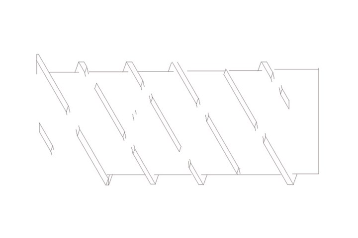
FIG 2 Saxton mixers have multiple flights with interrupting cuts that divide the melt to minimize fiber breakage and improve wetting out of the fibers.
A mixer type that I have had success with for low-shear mixing and good fiber wetting is the simple grooved-root design (Fig. 3). It can be designed to provide any level of shear and mixing, thereby avoiding the severe reorientations that can break fibers. Additionally, designs like this apply multiple low-shear cross-directional forces that can help to unbundle fibers as well as reduce the formation of agglomerates.
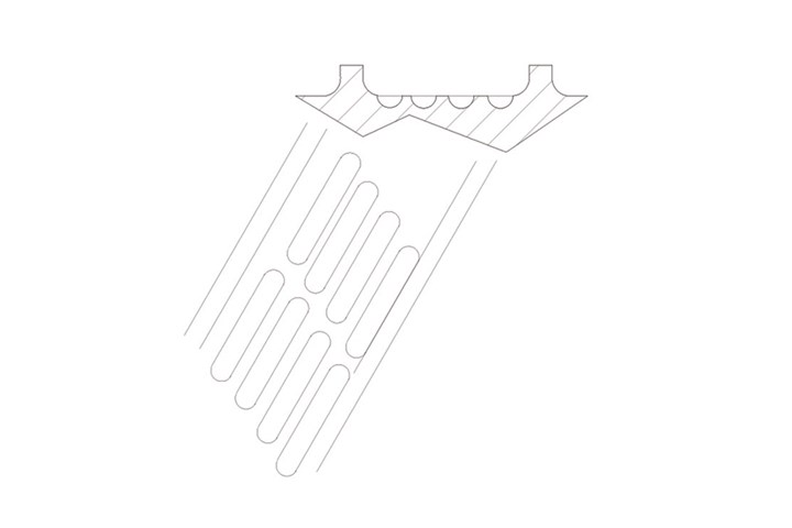
FIG 3 A simple grooved-root mixer design offers low-shear mixing and good fiber wetting. It can be designed to provide any level of shear and mixing, thereby avoiding the severe reorientations that can break fibers.
Regardless of the single-screw design, there is always some reduction in fiber length during the transition from solid to melt in the screw. However, with care in the design and operating conditions, suitable product physical property improvements can be obtained.
ABOUT THE AUTHOR: Jim Frankland is a mechanical engineer who has been involved in all types of extrusion processing for more than 50 years. He is now president of Frankland Plastics Consulting, LLC. Contact jim.frankland@comcast.net or (724)651-9196.
Related Content
How to Select the Right Cooling Stack for Sheet
First, remember there is no universal cooling-roll stack. And be sure to take into account the specific heat of the polymer you are processing.
Read MoreHow Polymer Melts in Single-Screw Extruders
Understanding how polymer melts in a single-screw extruder could help you optimize your screw design to eliminate defect-causing solid polymer fragments.
Read MoreWhy Are There No 'Universal' Screws for All Polymers?
There’s a simple answer: Because all plastics are not the same.
Read MoreSingle vs. Twin-Screw Extruders: Why Mixing is Different
There have been many attempts to provide twin-screw-like mixing in singles, but except at very limited outputs none have been adequate. The odds of future success are long due to the inherent differences in the equipment types.
Read MoreRead Next
In-Line Compounding of Long-Glass/PP Gains Strength in Automotive Molding
Another approach to long-fiber thermoplastic (LFT) molding is gaining credibility for producing a range of structural and semi-structural automotive parts. It is called direct LFT processing, and is already widely practiced in Europe.
Read MoreA Processor’s Most Important Job, Part 10: Fiber-Length Retention
Glass and carbon fibers are often used to increase material strength and modulus. To maintain these properties, the aspect ratio of these fibers must be maintained.
Read MoreWhy Long-Glass Molders Are Compounding In-Line
Compounding raw fiberglass directly into thermoplastic molded parts is growing rapidly in Europe, and now it’s coming here. D-LFT, as it’s called, promises to make large parts cheaper and stronger—but with new technological risks and higher up-front investment costs.
Read More
.jpg;width=70;height=70;mode=crop)
