The Scoop on Screws
The kind used as fasteners in molds, that is. Here are some design considerations to help you choose and use the right ones.
I value writing about the basics. I try to go into more depth than what you’ll find in some brochure, seminar, trade school, or even a college course—without being overly technical. I think it’s because I hate to hear someone say, “That’s the way we’ve always done it.” That’s not an answer. Well, at least not one based on any basic proven facts. The goal is to understand the basics, thereby reducing unnecessary problems with your molds.
So, when it comes to the basics, what could be more basic than a screw? Let’s start with the basic terminology—nut vs. screw. A screw is a type of fastener that is threaded into another part, such as a plate. A bolt requires a nut to form an assembly. We are all familiar with the phrase nuts and bolts, but nobody ever uses the phrase nuts and screws. There are not many bolts in an injection mold—even when the mold is made of a very soft material, like aluminum—but there sure are a lot of screws! I must admit, I am too old and too conditioned to start calling shoulder bolts by their correct name: shoulder screws. “But that’s what we’ve always called them.”
SCHS is the industrial acronym for Socket Head Cap Screw. This type of screw has an internal or recessed hexagonal shaped drive, as opposed to an external hex, slotted or Phillips-head drive. The beauty of this type of drive is there is no need to provide a large amount of clearance around the head. An SCHS requires only a few thousandths of an inch clearance, as opposed to a hex-head bolt that requires a socket wrench or box wrench for assembly. Therefore, SCHS’s can be spaced very close to one other. Since real estate is always at a premium in an injection mold, there’s really no better drive style.
A screw is a type of fastener that is threaded into another part, such as a plate, unlike a bolt, which requires a nut.
The only type of SHCS a moldmaker should use is made of heat-treated (32 - 43 Rockwell C, as per ASTM A574) medium carbon alloy steel with a Class 3A UNRC thread and a minimum tensile strength of 160,000 psi, which meets ANSI/ASME B18.3 specifications. The “R” in UNRC indicates the bolt was made using the rolling process. That process dramatically increases the strength and fatigue life of the screw. Rolled screws are about 20% stronger than Grade 8 bolts and 50% stronger than Grade 5 bolts.
While SHCS’s are not graded like hex bolts are, there can be a significant difference in strength between one manufacturer and another. It would be smart to compare the values of various suppliers to ensure you are getting the best bang for your buck. The “A” in Class 3A means that it is an external thread. If it were a “B”, it would mean an internal thread, like for a nut. The “3” in Class 3A describes the fit of the thread when mated with a tapped hole.
SHCS’s with Class 3 threads are so precise that they don’t even have enough room between the threads for plating or viscous coatings. The minimal amount of space between the male and female threads is only sufficient for lubricants and thread-locking compounds. Class 3 threads are used when safety is a design consideration.
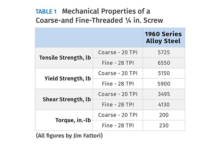
Coarse-thread SHCS’s are used predominantly in injection molds, even though fine-thread screws are stronger. Table 1 above shows the typical mechanical properties of a fine- and coarse-thread ¼-in. SHCS. As you can see, the fine- threaded screw is stronger in tensile, yield, and shear strength. Fine-threaded screws even have a higher recommended torque rating. Here’s why:
A fine-threaded screw, such as ¼-28, has the same major diameter as a ¼-20 coarse-threaded screw—0.250 in. But the finer thread has a larger root diameter, meaning the threads are not as deep. Therefore, the thread cross-sectional stress area is 0.032 in.2 vs. 0.036 in.2 for the coarse thread. That is why they are stronger. Additionally, since the lead angle of a fine-threaded screw is shallower than a course-threaded screw, it generates more holding force when torqued to the same value. After reading this you might think that fine-threaded screws are the best way to go for injection molds—but they’re not.
Coarse-threaded screws are the quickest for assembling and disassembling a mold—and time is money. They are less expensive and more resistant to corrosion than fine-threaded screws. They are also more forgiving if the threads get damaged. It’s easier and faster to tap a coarse-threaded hole, and the odds of cross threading a coarse-threaded screw are extremely low. These advantages outweigh the somewhat higher strength of fine-threaded screws.
Coarse-threaded screws are the better choice for injection molds.
While SHCS’s are made predominantly of heat-treated alloy steel, they are also available in 18-8, 316, and A286 stainless steel, 2024 and 7075 aluminum, as well as brass, titanium, nickel, bronze and various types of plastic. I would only use the heat-treated alloy-steel type of screw in an injection mold, even if it was to be used in a clean room for medical applications. But all these other types of materials have value in particular applications, such as using brass screws for electrical connections. It’s good to keep in mind that these various types are commercially available.
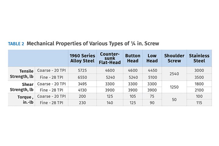
SHCS’s are available in various head configurations: standard, counter-sunk or flat head, button head, and low head. They are also configured as shoulder screws, which are often used in injection molds. When selecting the head and material type, keep in mind that there are strength differences between them, as shown in Table 2 below, which lists the typical mechanical properties for a ¼-in. SHCS. Keep in mind these typical values are based on using the correct drill and tap sizes.
It’s interesting to note that flat-head, button-head and low-head screws all have roughly the same strength, and that is not significantly lower than for standard-head screws—except for their torque values. Torque values are directly related to how much force a particular screw can apply to hold components together. If you ever want to use one of these other types of head configurations, keep in mind their reduced holding power. They should only be used in lower duty applications, or else you may need to add a few more screws to obtain the required total holding force.
Table 2 also shows how stainless-steel SHCS’s have roughly half the strength of the alloy-steel type. In other words, if you want to use stainless-steel screws in your mold, you will probably need twice as many, or use large-diameter screws to do the same job. Notice how the shoulder screws have very low mechanical property values. A lot of thought needs to be given when using this type of screw. I highly recommend you read my June and August 2019 articles on shoulder bolts, which should have been called shoulder screws.
That’s enough of the basics. Now let’s discuss various design aspects:
• The height of the head of an SHCS is typically the same as the screw’s diameter.
• The depth of the counterbore is typically 1/64 to 1/32 in. deeper than the height of the head.
• The clearance around the body is typically 1/64 in., although suppliers such as Holo-Krome, and Unbrako have recommended clearance drill and tap drill sizes, which can be either fractional, number, or letter sizes.
• The clearance around the head is typically 1/32 in.
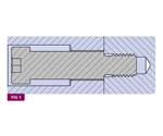
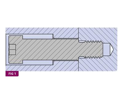
• It’s perfectly acceptable if the counterbore for the head of an SHCS extends beyond the edge of a mold component, as shown in Fig. 1.
Just make sure the sharp edges are radiused, so no one gets cut.
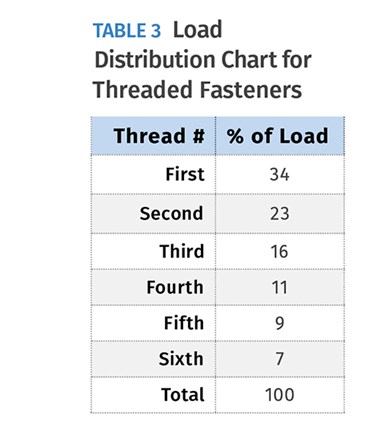
• The minimum amount of thread engagement required in carbon steel for maximum holding force is 6 divided by the pitch of the thread. That’s because the first six threads of a fastener account for 100% of its holding power, as shown in Table 3 below. For example, a ¼-20 SHCS should be engaged by 6 ÷ 20 = 0.30 in. However, it is better to use 9 divided by the pitch, to account for the lead-in or chamfer on both the screw and the threaded hole. With this amount of engagement, the screw will break at about the same time the threads will strip—depending on the material it is threaded into.
• The amount of thread engagement required in softer materials, such as aluminum, should be as much as twice that of carbon steel. So 18 divided by the pitch is a good guideline.
• Try not to have excessive screw engagement. Over time, the screws will rust. Excessive engagement can cause the screw to break during disassembly.
• A slight exception to the rule above is to try to avoid assembly errors, save time, and make life easier for the toolmaker. For example, if you have 10 screws that are 1-in. long and four screws that are 7/8-in. long, tap the hole for the 7/8-in.-long screws 1/8 in. deeper so all 14 screws are the same length.
• Increasing the amount of thread engagement does not increase the holding power. When more holding power is required, you need to add more or larger screws.
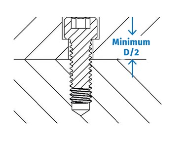
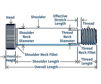
• There should be a minimum of half the diameter of the screw under the head, as shown in Fig. 2.
• Larger screws do not take up that much more room than smaller screws. Since larger screws have more holding power, fewer screws are often required.
• A screw achieves its holding force by being stretched as it is torqued. Shorter screws can’t stretch as much as longer screws. That’s why a shorter screw will come loose before a longer screw will. The length that can be stretched is the distance between the first engaged thread and the shoulder under the head, not the length of thread that is engaged.
• Always use standard-length screws. If you need more thread engagement, increase the depth of the counterbore for the head. If you need less engagement, add a counterbore in the threaded portion, as shown in Fig. 3.
• Some screws are fully threaded. Others—typically longer screws—have a solid shank portion above the threads that is actually a few thousandths larger than the major diameter of the threads. If the shank or non-threaded portion of a screw is too long, never run it though a tap to increase the thread length and never grind down the interfering portion of the shank. Either specify a fully threaded screw or add a counter-bore to the threaded hole as shown in Fig. 3.
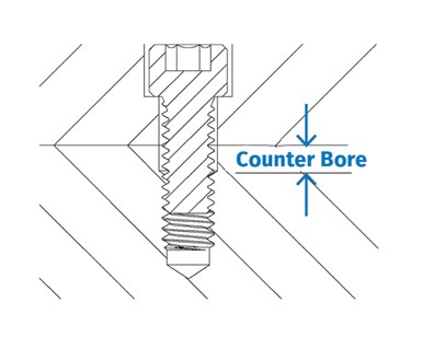
FIG 3 Counterbored tapped hole.
Thread engagement should be between 6 and 9 divided by the pitch of the thread.
• Adding a counterbore on all tapped holes, as shown in Fig. 3, is good standard practice. It protects the first thread, which makes it easier to assemble. It also increases the “free length” of the screw, which allows it to stretch more and apply more holding force.
• If you absolutely need to use a special screw, the screw and the corresponding threaded hole should be visibly marked or identified. Dykum sells a metal stain in assorted colors that works very well. It can take the guesswork out of a difficult assembly or mold changeover.
• Try not to use 7/16-in. or 9/16-in. diam. bolts. Most likely there won’t be any in the parts crib.
• Don’t locate screws randomly. They should be located symmetrically so the forces acting on them are also symmetrical.
• If you’re concerned about a plate deflecting, it is much better to use a thicker plate then it is to use more screws. In fact, the amount a plate can deflect is based on the thickness of the plate and the distance between the screws by the formula M/t3, where M is the center-to-center distance of the screws and t is the thickness of the plate. A thicker plate is usually less expensive than the additional labor required to install numerous screws, and it frees up more room for things like waterlines, interlocks, etc.
• One of the best places to use a thicker plate, or to add more screws, is between the ejector and ejector retainer plates. The forces applied to these plates by the molding machine’s knockout rods is localized or concentrated. Additional screws will help spread that load more evenly, especially when the force required to eject the parts is significant. Less deflection means longer pin and bearing life, as well as reduced down-flash from worn, elongated ejector-pin holes.
• Several types of steel, such as D-2, often shrink during heat treatment. It only takes a few thousandths of an inch to make assembling the mold very difficult. Therefore, for larger holes, specifying an oversized tap, such as an H7 (D7 for a metric thread), which is 0.0030 to 0.0035 in. larger than nominal prior to heat treatment is advisable.
Screws achieve their holding force by being stretched.
Now let’s discuss various assembly aspects:
• Although it is not customary to do so, all screws should be torqued. If they are not torqued, the screw that is the tightest will fail first and the remaining screws will have to bear the full load.
• You should be able to install a screw by hand until the head bottoms out. This will improve the accuracy of the torque value.
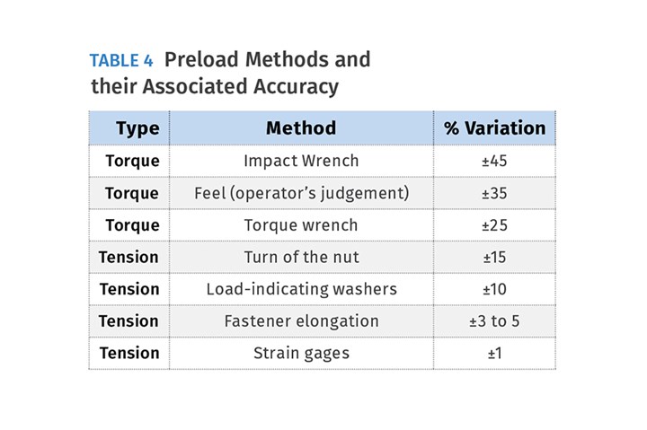
• It probably comes as no surprise that the torque accuracy of someone going by feel is very poor, but you would think using a torque wrench would be very accurate. As shown in Table 4, even torque wrenches can vary as much as ±25%. This is primarily due to the coefficient of friction. The torque applied to a fastener must overcome frictional forces before any preload takes place. If the assembly is not clean and lubricated, there is a considerable amount of friction at two locations: the bearing surface under the head and the thread-to-thread contact surfaces.
Approximately 50% of the torque applied to a screw is used to overcome the head-bearing friction and approximately 35% is used to overcome the thread -contact friction. Therefore, 85% of the torque value is strictly to overcome friction and only 15% is used to produce the preload on the screw. If these two frictional surfaces are lubricated, the friction is reduced by roughly 10% and thus, a substantially greater preload is obtained with the same amount of torque. Therefore, always lubricate the threads of any screw during assembly, as well as under the head. Lubrication also helps prevent rust, corrosion and seizing.
• When a screw is overloaded, it will almost always break at the root of the first engaged thread.
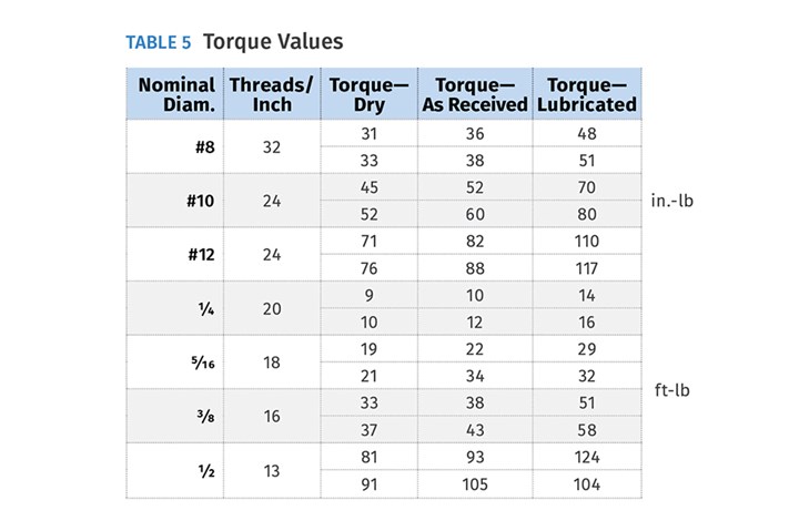
• As mentioned earlier, a screw achieves its holding force by being stretched as it is torqued. But what are the recommended torque values? That depends on whether the screws were cleaned and are now dry, if you just took them out of the box, or if you applied a lubricant before installing them. From Table 5 you can see these torque values are vastly different for each condition.
• If a screw has sufficient unengaged or free length, is properly lubricated, and is sufficiently torqued, there is no need to use a thread-locking compound or some type of lock washer. It is self-locking.
• If a screw is not sufficiently torqued, not only will it have little to no holding force, it may unscrew itself due to vibration.
• If a screw frequently unthreads itself or if it is in a position that major damage will occur if it does unthread, some method of securing the screw should be used. Such methods may include a thread-locking compound, pinning or keying the head of the screw, or even safety wiring the head of the screw to another screw or component.
• If a thread-locking compound, such as Loctite or Permatex is used, the screw and the tapped hole must first be degreased. These compounds will not work well on an oily surface.
• Blue is the most common type of thread-locking compound used for screw retention.
• Red is used for even greater holding power but requires heating with a torch to 500° F to remove the fastener.
• Green is a lower strength but can be used on parts that are already assembled because the compound will wick down the threads.
• Purple is a lower strength and is used for soft materials, such as aluminum.
• Thread-locking compounds are usually for one-time use. The threads need to be cleaned and dried before re-applying. Don’t forget to shake the bottle or tube before applying. Both types will set up in 10 min and fully cure in 24 hr.
• If a water leak develops between a threaded hole and a nearby rusted water line, braze a washer onto the head of the screw and use an O-ring under the washer to prevent the leak from traveling beyond the screw. You will have very little holding power, but you won’t have a water leak.
ABOUT THE AUTHOR: Jim Fattori is a third-generation molder with more than 40 years of experience in engineering and project management for custom and captive molders. He is the founder of Injection Mold Consulting LLC in Pennsylvania. Contact: jim@injectionmoldconsulting.com;
injectionmoldconsulting.com
Related Content
The Impact of Hydraulics on Tool Design -- Part 1 of 2
Get a better understanding of their use, proper sizing, and how the tool design and setup in the machine can impact failures in manufacturing.
Read MoreHow to Design Three-Plate Molds, Part 1
There are many things to consider, and paying attention to the details can help avoid machine downtime and higher maintenance costs, and keep the customer happy.
Read MoreBack to Basics on Mold Venting (Part 2: Shape, Dimensions, Details)
Here’s how to get the most out of your stationary mold vents.
Read MoreHow to Select the Right Tool Steel for Mold Cavities
With cavity steel or alloy selection there are many variables that can dictate the best option.
Read MoreRead Next
Why Shoulder Bolts Are Too Important to Ignore (Part 2)
Follow these tips and tricks for a better design.
Read MoreWhy Shoulder Bolts Are Too Important to Ignore (Part 1)
These humble but essential fasteners used in injection molds are known by various names and used for a number of purposes.
Read MoreLead the Conversation, Change the Conversation
Coverage of single-use plastics can be both misleading and demoralizing. Here are 10 tips for changing the perception of the plastics industry at your company and in your community.
Read More

