Melt Flow Rate Testing—Part 4
Few molders perform the test in-house. Of those that do, most don't understand why they are doing it or what they are measuring.
While melt flow-rate testing is not extremely difficult, and the equipment is not very costly, few molders perform the test in-house. Of those that do, a relatively small percentage of them understand why they are doing it or what they are measuring. As we have mentioned previously, most material suppliers specify and control their products to a melt flow-rate (MFR) specification because they know that it is related to the average molecular weight (MW) of the polymer they are producing. If the MFR is consistent, the average MW is consistent.
But many molders who check their incoming materials to verify the certifications they receive believe that they are testing to ensure process consistency. This belief is based on a poor understanding of the relationship between the MFR value and the actual viscosity of the material at processing conditions.
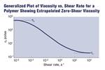
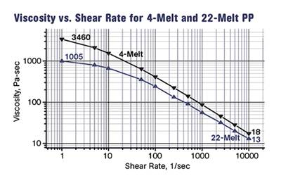
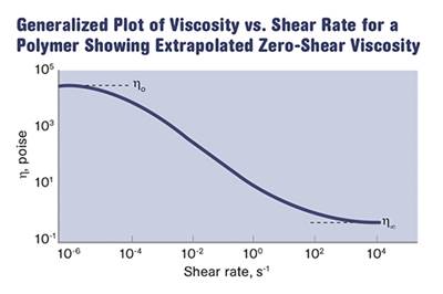
The capillary rheometry curves we have shown in previous columns (see Editor's Pick top right) illustrate that the viscosity of a polymer is dependent upon the shear rate. We also know that a component of the shear rate is the volumetric flow rate of the material. The other component is the geometry of the flow path, which should be a constant for any given mold. Of course, the shear rate varies with location in the flow path. It is different in the runner than it is at the gate, for example.
But for any given location within the flow path there is the expectation that the cross-sectional area of the flow path remains the same. Therefore, the only process variable that can influence the shear rate is the flow rate of the material as it is filling the mold. Flow rate is controlled by a machine parameter known to processors as injection speed. On today’s machines the technician selects the injection speed by finding the appropriate screen and entering a setting that is usually given as a linear distance per unit time such as in./sec or mm/sec.
Let’s assume for a moment that the setup document for a particular mold running in a particular machine calls for a first-stage injection speed of 3 in./sec. If the stroke distance from the beginning of the injection process to the point at which the machine transfers from first to second stage is 6 in., then the fill time should be 2 sec. Very few processors ever check to see if this is actually the case, even though fill-time clocks accurate to two or three decimal places are standard equipment on modern molding machines. Processors tend to enter the setpoint and trust that the machine is doing what it is told to do.
There are a number of factors that could prevent the machine from responding the way it should, but in the end these all boil down to a lack of pressure needed to achieve the desired velocity. Processes that run without an abundance of first-stage injection pressure are called pressure-limited.
Viscosity is defined as resistance to flow. It can be thought of as the product of the pressure applied to the fluid and the time over which this pressure is applied. To move a fluid of higher viscosity a certain distance, it is necessary to either use more pressure over a particular period of time or apply the same pressure over a longer period of time. The SI units for viscosity, Pascal-seconds (Pa-s), reflect this relationship.
If a molding machine is to run in a velocity-controlled mode it must be set up to provide more pressure than is needed to deliver the desired volume of material to the mold in a fixed time. In this way, when the viscosity of the material increases due to a change in molecular weight, the pressure will increase proportionally but the time will remain the same. If the time needed to deliver the material remains the same, then the shear rate remains the same and will limit any change in viscosity to the inherent effect of the higher MW. The latter contribution is relatively small when the material is flowing at velocities typical of first-stage injection.
If the pressure is limited, either by the design of the molding machine or by the manner in which the machine has been set up, then when the material viscosity increases, the time required to deliver the material to the mold becomes longer. In other words, the injection speed slows down all by itself. A slower injection speed translates to a lower shear rate and this exaggerates the difference in the viscosity of the material—just like the MFR test does.
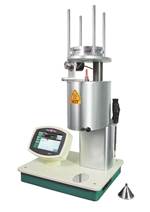
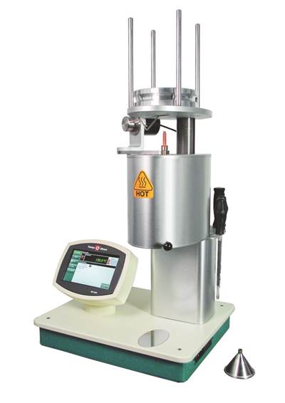
The MFR instrument is pressure-limited. A constant load is applied and the operator simply observes the behavior of the material. If it is true that the molding machine in the plant “notices” the difference in the MFR of the material, it is because the machine is set up like the MFR tester, to be pressure-limited.
To put it another way, a velocity-controlled process minimizes the effect of changing viscosity on the stability of the process, while a pressure-controlled process exaggerates this effect. Normal MFR variations only influence the process if the machine runs with a limit on the available pressure.
Lot changes in raw material are not the only possible cause of a change in the viscosity. If regrind is blended into the virgin material, then fluctuations in the amount of regrind or changes in the MW of that regrind can cause variations.
In addition, many polymers exhibit changes in melt viscosity due to variations in their moisture content. For example, a 30% glass-filled PET polyester dried to 50 ppm may have a viscosity 10-15% higher than that same material dried to 200 ppm. Both of these materials are considered to be adequately dry for most applications, but they may process differently, depending upon how the machine is set up. This effect is even more pronounced in nylons.
That is the reason for a lot of the folklore in the industry about nylon materials being “too dry.”
In short, if the molding process is properly established, typical fluctuations in MFR for a given grade of material should have no significant effect on the process or the parts coming out of that process, because the conditions of the MFR test do not resemble those of the molding process until you reach the pack and hold phase. If you are doing things correctly, by that point your mold cavity or cavities should be almost (but not completely) full. A robust process, properly established in a capable molding machine, should handle changes in viscosity much larger than the typical lot-to-lot variation observed in a given grade of material.
So if the MFR test is not intended as a gauge of processability, then what is it supposed to be used for? Next month we will address this topic.
Related Content
Fundamentals of Polyethylene – Part 6: PE Performance
Don’t assume you know everything there is to know about PE because it’s been around so long. Here is yet another example of how the performance of PE is influenced by molecular weight and density.
Read MoreThe Effects of Stress on Polymers
Previously we have discussed the effects of temperature and time on the long-term behavior of polymers. Now let's take a look at stress.
Read MoreWhere and How to Vent Injection Molds: Part 3
Questioning several “rules of thumb” about venting injection molds.
Read MoreBack to Basics on Mold Venting (Part 2: Shape, Dimensions, Details)
Here’s how to get the most out of your stationary mold vents.
Read MoreRead Next
Melt Flow Rate Testing–Part 1
Though often criticized, MFR is a very good gauge of the relative average molecular weight of the polymer. Since molecular weight (MW) is the driving force behind performance in polymers, it turns out to be a very useful number.
Read MoreMelt Flow Rate Testing – Part 2
To fully appreciate the strengths and weaknesses of the melt-flow-rate (MFR) test it is important to know something about the way the test is performed.
Read MoreMelt Flow Rate Testing—Part 3
There is a well-established relationship between something called the weight-average molecular weight of a polymer and a parameter known as the zero-shear viscosity.
Read More
.jpg;width=70;height=70;mode=crop)
